February 2012 10 80-0180-351 Rev. E
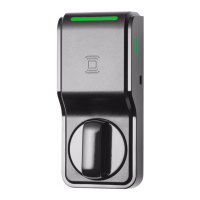
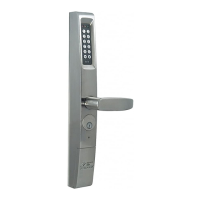
STEP 4 HANDING THE eForce
®
150
The eForce
®
150 is shipped in a non-
handed neutral position with the access
cover off as shown.
To hand the eForce
®
150, rotate the
handle until it clicks into the horizontal
position.
Proceed to step 5 if installing the
3090-02!
The output hub, located on the back of the eForce
®
150,
is shipped with a clockwise rotation as viewed from rear.
In some instances, this rotation must be changed to
match the device and/or hand of the door (refer to
Handing Setup Chart).
To change rotation, insert a flat screwdriver into the output hub (FIG. 12)
located on the back of the eForce
®
150 and turn approximately 270° Clock-
wise or Counter-Clockwise.
This will reconfigure the unit to the opposite rotation.
HANDING SETUP CHART
DEVICE TYPE
LEFT HAND REVERSE
ROTATION
RIGHT HAND REVERSE
ROTATION
SVR CLOCKWISE CLOCKWISE
Mortise Latch COUNTER-CLOCKWISE CLOCKWISE
CVR CLOCKWISE CLOCKWISE
Rim COUNTER-CLOCKWISE COUNTER-CLOCKWISE
FIG. 12
NOTE:
Hubs that have (+) shape are for use with deadlatches & exits only.
Hubs that have (-) shape are for use with deadbolts only.
80-0180-351 Rev. E 7 February 2012
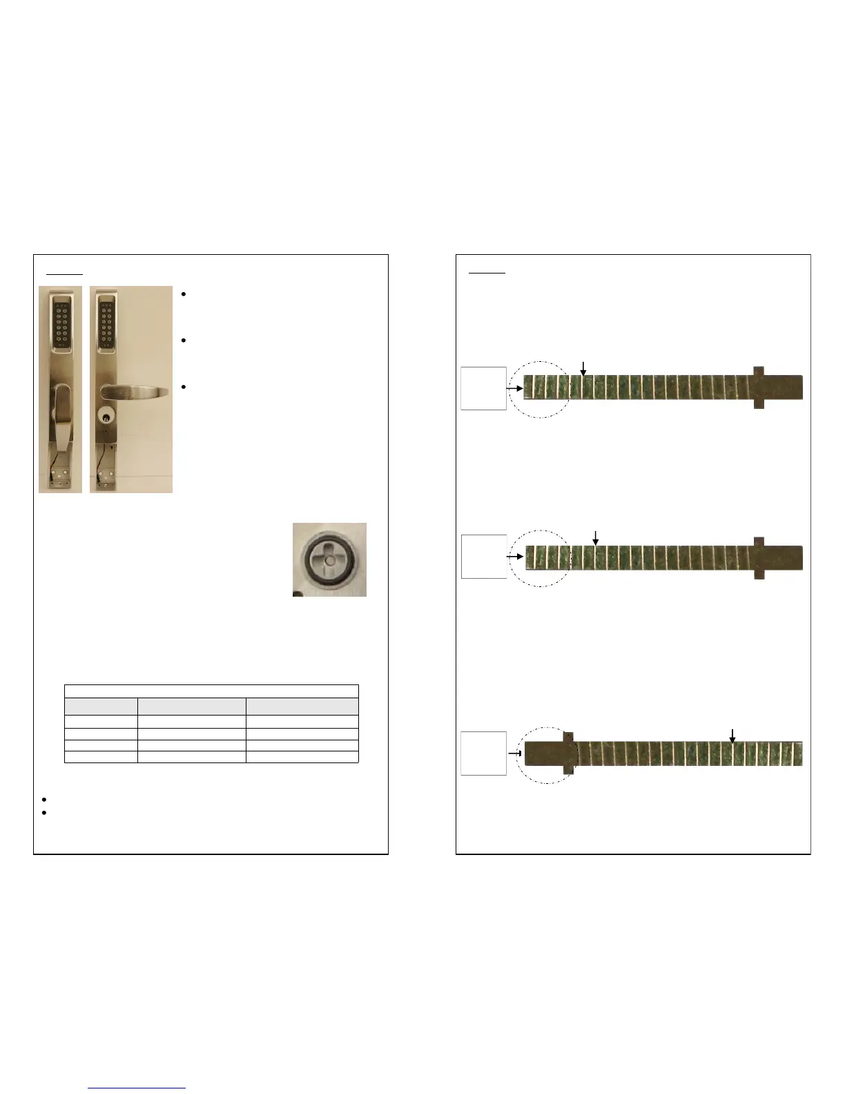
STEP 2 SPINDLE PREPARATION (For 1-3/4” doors)
For Adams Rite MS1850 Deadbolts, 4500/4900 Deadlatches, & 8000
Series Mortise Exit Devices:
Snap-off spindle at fifth (5th) notch as shown in FIG. 4. For 2” thick door add
one notch.
For Adams Rite 8600 Concealed Vertical Rod Exit Devices:
Snap-off spindle at sixth (6th) notch as shown in FIG.5. For 2” thick doors add
two notches.
For Adams Rite 8000 Series Surface Vertical Rod & Rim Exit Devices,
Yale 7200 Series Narrow Stile Exit Devices, Corbin Russwin ED4000
Series, and SARGENT 8500 Narrow Design Rim Exit Devices:
Snap-off spindle at fourteenth (14th) notch as shown in FIG. 6. For 2” thick
doors add two notches.
FIG. 6
Insert “T”
end into
exit devices
Fourteenth notch
FIG. 5
Sixth notch
Insert Flat
end into
exit devices
FIG. 4
Fifth notch
Insert Flat
end into
exit devices
 Loading...