February 2012 6 80-0180-351 Rev. E
STEP 1 DOOR PREPARATION
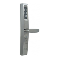
FIG. 2
Select the stick-on template to match the applica-
tion.
For Yale, Corbin Russwin and SARGENT exit
devices, use template 80-0180-396-01.
Mark the backset and horizontal centerlines.
Apply clear template over the centerline marks
(FIG. 2)
Center-punch four (4) referenced mounting holes
and remove template.
Drill holes at center-punch locations using a ¼” drill
bit.
Install Rivnuts. Refer to instructions supplied in
Rivnut kit.
Install mounting bracket (Item 1) with two (2) each of
#10-32 x 5/8” (Item 2) pan head screws. (FIG. 3)
FIG. 3
80-0180-351 Rev. E 11 February 2012
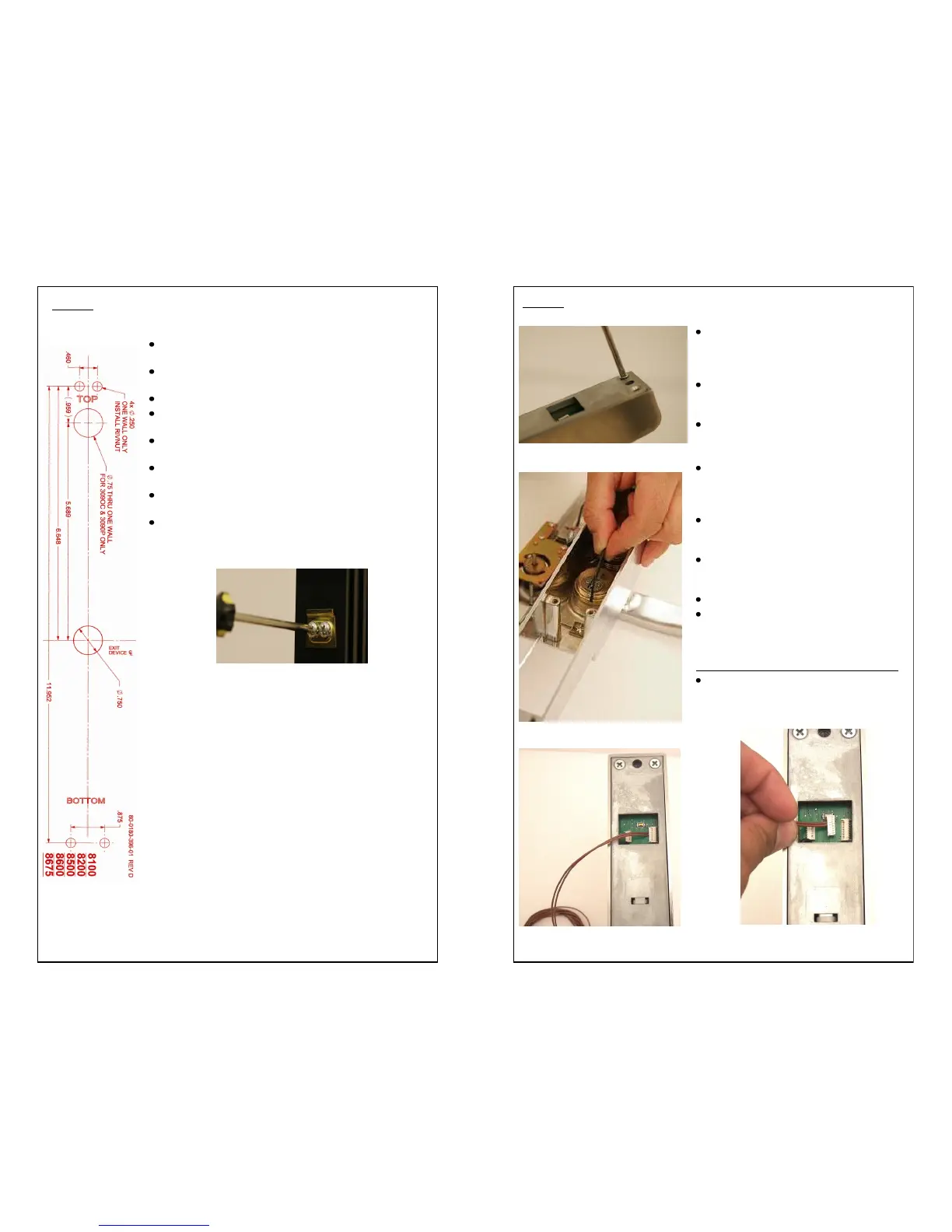
STEP 5 MORTISE CYLINDER INSTALLATION
Using a Philips Head Screwdriver, re-
move the eight (8) #10-32 x 5/8” screws
on the back of the eForce
®
150 and
gently lift the back plate off the housing.
CAUTION! There are wires connecting
the housing and back plate assembly.
Handle with care.
Do not over-tighten!
Install Cylinder into housing. Secure
and fasten with supplied locking ring
using locking ring spanner tool.
(FIG. 14)
Gently place back plate back on hous-
ing and secure with eight (8) #10-32 x
5/8” screws.
CAUTION! There are wires connecting
the housing and back plate assembly.
Handle with care.
Do not over-tighten!
Do not use Dummy Cylinder!
Remote Switch Kit RSK-3090 (Optional)
For applications that require a remote
activation switch, plug the RSK-3090
into the board as shown in Fig. 15 & 16.
FIG. 13
FIG. 14
FIG. 16
FIG. 15
 Loading...