Do you have a question about the Assa Abloy 835C-50 and is the answer not in the manual?
Details the physical installation steps for the lock case and striking plate, including drilling and rebates.
Explains how to connect the lock to the Hi-O Bus using four cables and specifies cable types.
Explains how to configure the lock's fail-safe or fail-secure mode using DIP switches on the casing.
Details how to adjust screws for fixed or split spindle operation, affecting manual/electrical control.
Guides on connecting and setting up the lock case with the I/O Box, including DIP switch settings.
Details setting up the lock case with DAC564/DAC530, including DIP switch and LED indications.
Provides instructions to reset the lock to factory settings using the bolt and group switch.
Explains how to configure the 835C-50 for SSF 3522 mode and describes relay operations.
Illustrates the connection diagram for 813C, 815C, 820C, 825C, 835C with the DAC564.
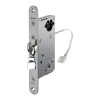
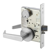
The ASSA ABLOY motor locks, including models 813C-50, 815C-50, 820C-50, 825C-50, and 835C-50, are advanced access solutions designed for various door types and security requirements. These motor locks are part of the ASSA ABLOY Opening Solutions range, emphasizing safety, security, and user experience.
These motor locks are designed to provide controlled access, offering both fail-locked and fail-unlocked operations, which can be configured via DIP switches on the lock casing. This setting determines whether the door remains locked or unlocked in the event of a power cut. The locks feature a latch and, in some models, a hook bolt, which can be reversed to suit the door's opening direction. Handle operation can be set for either fixed or split spindle configurations, allowing for different access control scenarios (e.g., locked outside, manually operated inside).
The locks incorporate a door position sensor, located in-line with a datum mark on the lock face plate. When used, a magnet is fitted to the striking plate at the same height as the datum mark to ensure proper sensing. The motor locks can be integrated into a Hi-O Bus system, connecting via four cables (two for power, two for communication). They are compatible with I/O Box 350 and DAC564/DAC530 control units, enabling standalone operation or integration into a larger access control system.
Specific models like the 820C/825C offer a deadlocking condition setting, allowing the lock to report deadlocking based on either the dead-latching snib or the latch being locked, preventing unlocking from outside when manually locked from inside. The 835C-50 model, when configured in SSF 3522 mode, provides specific relay operations for deadlock indication, inside handle activation, error reporting, and forced relay indication.
The ASSA ABLOY motor locks operate on a supply voltage of 12-24 V DC (min 11V, max 27.8 V DC). Power consumption varies depending on the operation and voltage:
The maximum cable length for the EA226 cable is 50m. Recommended cable areas for 12V operation are: 20m (0.3 mm²), 30m (0.4 mm²), 40m (0.5 mm²), and 50m (0.6 mm²).
The locks are designed for installation in single or double doors made from wood, aluminium, or steel, with a maximum door weight of 200 kg. They are certified under CE cert. CPR 21-524 and SSF 3522 class 3, with SS-EN 14846 compliance for specific models. The operating temperature range is -30°C to +70°C, with external heating required below -30°C for the reader. Storage and transport temperature range is -50°C to +70°C.
| Brand | Assa Abloy |
|---|---|
| Model | 835C-50 |
| Category | Locks |
| Language | English |