The SARGENT BHL Trim for Mortise Locks 8200 Series is an installation guide for a door lock trim designed for mortise lock applications. This document provides comprehensive instructions for installing and configuring the BHL trim, ensuring proper functionality and adherence to safety standards.
Function Description:
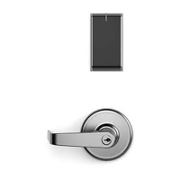
The SARGENT BHL Trim is a component of a mortise lock system, specifically designed for the 8200 Series. It includes the outside and inside lever assemblies, roses, adapter plates, and associated hardware. The trim's primary function is to provide the aesthetic and operational interface for the mortise lock, allowing users to operate the latchbolt and engage/disengage the locking mechanism. The installation process covers various lock functions, including storeroom, office/entry, service, communicating/exit, utility, closet, classroom, and classroom security/intruder latchbolt locks. The guide details how to correctly hand the lock and the roses, ensuring compatibility with the door's swing direction and the desired security configuration. It also explains how to change the lock function by adjusting a green catch screw on the lockcase, which dictates the locking behavior (e.g., always locked, always unlocked, or key-controlled).
Important Technical Specifications:
- Compatibility: Designed for SARGENT 8200 Series Mortise Locks.
- Door Thickness: Standard #41 Cylinder is suitable for both single and double cylinder functions for 1-3/4" thick doors.
- Thumb Turn: A 130 KB thumb turn is used with rose trim only. Escutcheon trims requiring thumb turns must be preassembled at the factory.
- Trim-one-side functions: Always require an inside trim assembly, which can be used on either the inside or outside of the door. A specific part number (82-4611) is provided for ordering the Trim one-side kit (for all trim except PT or FE).
- Screw Types: The installation utilizes Phillips head screws (#2), Torx Tamper Resistant Drivers (T-20 and T-10), and a 5/64" Hex Key Driver. Button head screws (6-32 X 7/16 LG) are used to secure the roses. Machine screws (#8-32x5/8) are used for the inside rose/adapter plate assembly.
- Drill Bit Sizes for Door Preparation (Turn-piece functions): One middle hole of 0.290" and two outer holes of 3/8" are drilled halfway through the door.
- Drill Bit Sizes for Door Preparation (Coin-turn functions): Two holes of 1/8" are drilled halfway through the door.
- Lock Handing: The red surface of the locking piece must face the secure side of the door. The hub position for 04, 06, 13, and 31 functions must be at a 45° angle.
- Latch Orientation: The beveled surface of the latch must face the strike. The deadlatch is self-adjusting.
Usage Features:
- Clear Handing Instructions: The manual provides detailed visual aids and steps for determining and setting the correct handing for both the lockbody and the roses (left-hand, right-hand, reverse bevel). This is crucial for ensuring the lock operates correctly with the door's swing.
- Function Changeability: The ability to change the lock's function (e.g., from storeroom to office) by repositioning a green catch screw offers flexibility for various applications without needing to replace the entire lock.
- Turn-piece and Coin-turn Options: The guide includes specific instructions for preparing the door for turn-piece and coin-turn functions, catering to different operational requirements for privacy or emergency access.
- Cylinder Installation: Detailed steps for installing cylinders, including proper orientation and tightening, ensure secure and functional key access. The manual explicitly warns against incorrect cylinder rotation.
- Adapter Clutch System: The installation of an adapter clutch into the mortise lock hub is a key step, ensuring smooth operation of the lever.
- Bushing Verification: Instructions for verifying the tightness and orientation of the bushing are provided to prevent spindle play and ensure proper lever function.
Maintenance Features:
- Self-Adjusting Deadlatch: The deadlatch feature is self-adjusting, reducing the need for manual calibration during installation or over time.
- Robust Construction: The use of security Torx screws for attaching the inside rose assembly and mounting posts for the outside adapter plate and rose suggests a design focused on durability and tamper resistance.
- Grease Application: The instruction to apply grease to specific surfaces (e.g., spindle) indicates a design consideration for smooth operation and longevity of moving parts.
- Detailed Troubleshooting (Implied): While not explicitly a troubleshooting guide, the detailed, step-by-step instructions and warnings about improper installation (e.g., "Improper installation may result in damage to lock and void factory warranty") serve as a preventative measure, guiding installers to avoid common errors that could lead to maintenance issues.
- Rehanding Capability: The "Outside Lever Rehanding (Optional)" section allows for field adjustment of the outside lever, which can be beneficial if the door's handing changes or if a universal part needs to be adapted. This reduces the need for specialized parts for different handings.