Do you have a question about the Assa Abloy Sargent IN100 and is the answer not in the manual?
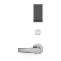
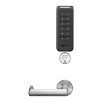
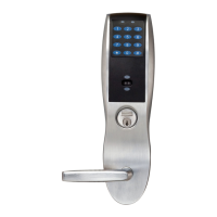
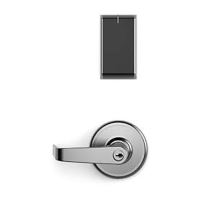
Provides an overview of the IN100 mortise lock with Aperio technology.
Details physical and compliance specifications for the lockset.
Outlines power input, supported credentials, and wireless network features.
Verify door hand/bevel and clear holes for installation.
Install the strike in the door frame according to the provided diagram.
Install latch with beveled bolt facing strike, do not tighten screws completely.
Push wires through raceway, install DPS and magnet into door frame.
Adjust lock preset for door thickness if necessary, or proceed to installation.
Remove outside lever and adjust through-bolts for proper door thickness.
Rotate mounting plate to align through-bolt holes or adjust for door thickness.
Feed harness, slide lockbody into cross-bore, ensuring engagement with latch.
Slide inside rose assembly, position ground lug, secure with through-bolts.
Verify spacer bushing, place rose, and attach inside lever.
Orient reader, feed cable, and install reader to the outside of the door.
Secure DPS, lock body, and power connectors to terminals. Tuck excess cable.
Connect the 4-pin DPS connector to its terminal.
Connect the 10-pin lock body assembly connector to its terminal.
Align mounting assembly and tighten through-bolts to secure the reader.
Connect the 24-pin card reader connector.
Insert controller tabs into slots and pivot bottom until it snaps into place.
Place six AA alkaline batteries in the compartment, observing polarity.
Hook top edge of cover onto mounting plate and secure with allen wrench.
Describes optical schemes for the communication hub LED.
Details LED indications used during lock maintenance actions.
Explains LED indications for Ethernet link and communication status.
Details lock LED indications for various operational states.
Details LED indications for card access, granted, denied, and force closed states.
Describes special LED schemes used during lock maintenance actions.
Explains LED indications for power-on self-test results.
Indicates low battery voltage, backward battery, or no power-on self-test.
Indicates power-on self-test passed successfully.
Indicates fatal, cable, or mechanical errors detected during self-test.
| Brand | Assa Abloy |
|---|---|
| Model | Sargent IN100 |
| Category | Locks |
| Power Source | Battery |
| Audit Trail | Yes |
| Door Thickness | 1-3/4" to 2-1/4" |
| Finish | Satin Chrome |
| Access Method | Keypad |
| Users | Up to 5, 000 |
| Backset | 2-3/4" |
| Operating Temperature | -4°F to 151°F (-20°C to 66°C) |
| Handing | Reversible |
| Construction | Heavy-duty |
| Compliance | ANSI/BHMA A156.25 |