Do you have a question about the Assa Abloy Sargent Aperio IN100 and is the answer not in the manual?
Equipment compliance with Class B digital device limits and measures to prevent interference.
Apparatus meets Canadian interference regulations and conditions for operation.
Basic precautions for handling electronic components to avoid ESD damage.
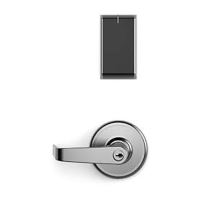
Steps for verifying door hand and preparing the door for lock installation.
Instructions on how to reverse the hand of the lock body and latch.
Guidance on setting the DIP-switch configurations on the mortise lock body.
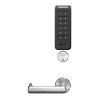
Procedure for installing the door position switch and its magnet.
Steps for feeding the wire harness and inserting the lock body into the mortise pocket.
Instructions for installing the cylinder on the outside of the door.
Steps for assembling the outside lever, spindle, and adapter onto the door.
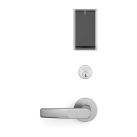
Procedure for attaching the inside rose and lever to the spindle.
Instructions for installing the thumb turn and testing its function.
Steps for securing the front plate using Phillips head screws.
Routing reader harness and DPS connectors through the inside mounting assembly.
Connecting DPS, lock body, and power connectors, and securing the mounting plate.
| Model | Aperio IN100 |
|---|---|
| Category | Locks |
| Power Supply | Battery Powered |
| Audit Trail | Yes |
| Type | Wireless |
| Battery Life | Up to 2 years |
| Operating Temperature | -20°C to +60°C (-4°F to +140°F) |
| Compatibility | Compatible with access control systems |
| Locking Mechanism | Mortise |
| Door Thickness | 1 3/4" (44mm) to 2 1/4" (57mm) |
| User Capacity | Determined by access control system |
| Certifications | UL294 |
| Brand | Assa Abloy Sargent |
| Finish | Multiple options available |