22 1-800-810-WIRE • www.sargentlock.com • A8190B
Copyright © 2016, Sargent Manufacturing Company, an ASSA ABLOY Group company. All rights reserved.
Reproductions in whole or in part without express written permission of Sargent Manufacturing Company is prohibited.
07/31/16
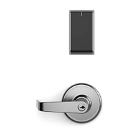
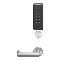
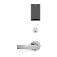
IN100 Mortise Lock
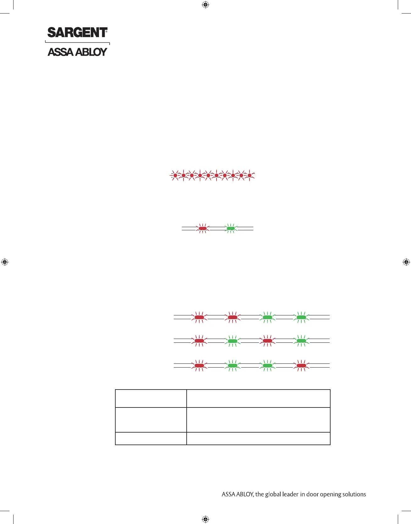
Lock Self-Test LED indication
After replacing batteries, a Power on Self Test (POST) is performed. The result is indicated
using a series of red and green LED flashes as described by the figures below.
8.3.1 Battery not fully charged
8.3.2 Test pass
1 red (1s) + 1 green (1s), Power on self-test passed, see table below.
Error in lock, Ten red flashes (.125 sec. each)
maintenance required
(Repeated every 10 sec. if lock can’t close)
LED indication after power up/replacement of the battery
Figure 6. Lock POST LED
indication
8.3.3 Test fail
1 red (1s) + 3 blinks (500ms, green or red), at least one test failed (red), see table below.
FATAL ERROR
CABLE ERROR
MECHANICAL ERROR
FATAL ERROR Tests core functionality - MCUs, memory and
internal communication, etc.
CABLE ERROR Tests communication between the different
parts in the system, i.e. different boards
connected with a wire.
MECHANICAL ERROR Test related to moving parts of the lock.
1 sec 0.5 sec 0.5 sec 0.5 sec
One red, one green flash
POST Successful
(1 second)
If a fatal error is detected the lock will enter an Error state and continuously indicating
fatal error and will not read cards nor unlock.
Error in lock is an indication -10 quick (125ms) red blinks, that either new batteries are not at the
right voltage or a backward battery has been installed; battery not fully charged; energy counter
not reset or no Power on self-test done.
 Loading...