Copyright © 2016, Sargent Manufacturing Company, an ASSA ABLOY Group company. All rights reserved.
Reproductions in whole or in part without express written permission of Sargent Manufacturing Company is prohibited.
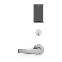
IN100 Cylindrical Lock
Inside of
Door
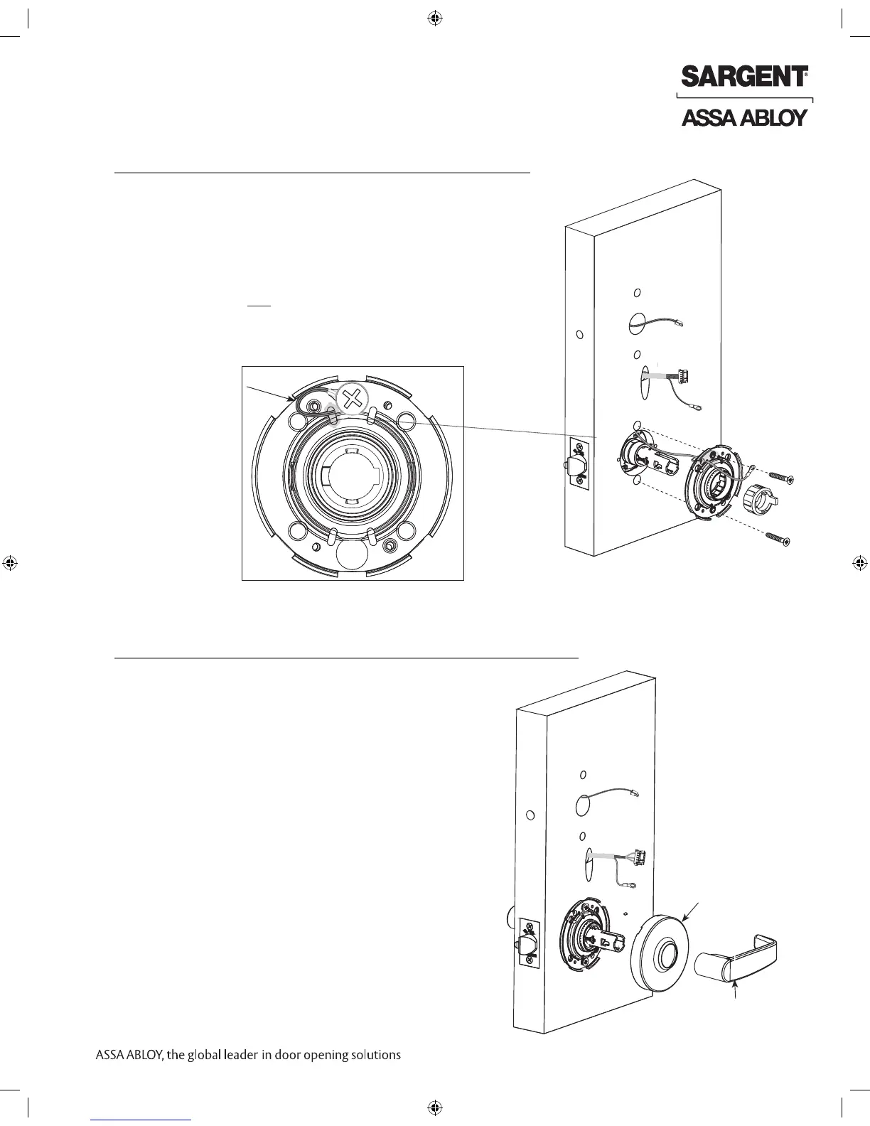
9 Assemble Inside Trim
1. Verify spacer bushing is inserted horizontally and
aligned with lever (Fig. 9).
2. Place rose over shaft of lockbody against the
surface of the door; hand-tighten, turning clockwise.
3. Attach lever. Push until engaged.
8 Secure Lock to the Door
1. Slide inside rose assembly and spacer bushing over lockbody.
2. Position ground lug between (top) #10-32x1-1/4” through-bolt
and rose assembly (Fig. 8A).
NOTE: Proper placement of ground wire (Fig. 8B) will prevent
pinching/damage to the ground wire.
3. Secure rose assembly with (2) #10-32x1-1/4” through-bolts.
4. Secure latch by fully tightening (2) #6 x 3/4” self-tapping screws
(refer to previous section 3 - Install Latchbolt).
Fig. 8A
Inside of Door
Fig. 8B Detail
Ground Wire
NOTE: Cable lengths exaggerated for illustrative purposes.
Fig. 9
Rose
Inside lever
 Loading...