EasyManua.ls Logo

Assa Abloy 8800 Series - User Manual

Assa Abloy 8800 Series
8 pages
Print Icon
To Next Page IconTo Next Page
Loading...
8800 Series Mortise Lock
Used with Sectional Trim and V Series Indicators
Installation Instructions
80-8800-0016-000 10/23
1-800-438-1951 • www.assaabloy.com
Copyright © 2020, 2023, ASSA ABLOY Access and Egress Hardware Group, Inc. All rights reserved. Reproduction in whole
or in part without the express written permission of ASSA ABLOY Access and Egress Hardware Group, Inc. is prohibited.
WARNING
This product can expose you to lead which is known to the state of California to cause cancer and birth defects or other
reproductive harm. For more information go to www.P65warnings.ca.gov.
WARNING
Attention Installer: Any retrot or other eld modication to a re rated opening can potentially impact the re rating of the opening,
and ASSA ABLOY makes no representations or warranties concerning what such impact may be in any specic situation. When
retrotting any portion of an existing re-rated opening, or specifying and installing a new re-rated opening, please consult with a
code specialist or local code ofcial (Authority Having Jurisdiction) to ensure compliance with all applicable codes and ratings.
Question and Answer IconNeed help?

Do you have a question about the Assa Abloy 8800 Series and is the answer not in the manual?

Summary

Tools Required

Indicator Variants

Lock Set Configuration

Rehanding Indicator

Installation

Prepare Door for Mortise Lock

Prepare door for function holes, size, and location according to marker template.

Install Lock

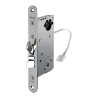
Verify strike location, clean pocket, and slide lock into door pocket.

Prepare Door for Indicator

Use template guide and marks to position indicator holes on the door.

Install Levers

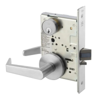
Insert mounting plate, align, fasten, install roses, bushings, and levers.

Install Indicator Mounting Plate

Align and fasten inside mounting plate securely with screws.

Install Indicator Assembly

Assemble indicator onto mounting plate and secure with screws.

Install Cylinder

Thread cylinder into lock until flush and tighten clamp screw.

Install Outside Front

Tighten lock screws and attach outside front with screws.

Perform Functional Check

Verify lock operation, key function, deadbolt, levers, and indicator status.

Indicator Parts List

Overview

The document describes the 8800 Series Mortise Lock, designed for use with sectional trim and V Series indicators. This product is now offered under the ASSA ABLOY ACCENTRA™ brand.

Function Description

The 8800 Series Mortise Lock is a door locking mechanism that integrates with various indicator types to display the status of a door (e.g., locked, unlocked, vacant, occupied). It is designed for installation on doors that may or may not be fire-rated, with specific instructions for preparing the door, installing the lock body, and integrating the indicator assembly and levers. The lock supports different input mechanisms for the indicator, including cylinder, thumbturn, coin turn, and blank/no input options, allowing for flexible access control and status display configurations.

Important Technical Specifications

  • Product Series: 8800 Series Mortise Lock
  • Compatibility: Designed for use with Sectional Trim and V Series Indicators.
  • Door Thickness: Standard thickness doors are 1-3/4". For other thicknesses, contact the factory.
  • Screws:
    • Lock screws: #12x1-1/4" wood screws or #12-24x1/2" machine screws for temporary installation; #8-32 x 1/4" flat head screws for outside front.
    • Mounting plate screws: #8-32 x 1-1/4" screws.
    • Indicator assembly screws: #8-32 x 5/8" screw for top, #8-32 x 3/8" screw for bottom (Torx security screws recommended).
    • Cylinder clamp screw: #2 Phillips screwdriver.
  • Drill Bits: 3/32" drill bit for indicator holes.
  • Wrenches: 1/8" Allen wrench.
  • Drivers: T-20 Torx screw with tamper pin driver.
  • Indicator Variants (Part #s):
    • Sectional Escutcheon - Cylinder: 81-0472-4000 x finish
    • Sectional Escutcheon - Coin Turn: 81-0471-4000 x finish
    • Sectional Escutcheon - Thumbturn: 50-8800-0364 x finish
    • Sectional Escutcheon - No Input/Blank: 81-0473-4000 x finish
    • Indicator Window: 856F049
    • Indicator Display Assembly (various status displays):
      • Green Unlocked / Red Locked: 82-5602-4000
      • Green Vacant / Red Occupied: 82-5603-4000
      • Green Unlocked Icon / Red Locked Icon: 82-5604-4000
      • White Unlocked / Red Locked: 82-5605-4000
      • White Vacant | Red Occupied: 82-5606-4000
      • White Unlocked Icon | Red Locked Icon: 82-5607-4000
      • Green Ouvert | Red Fermé: 82-5684-4000
      • Green Libre | Red Occupée: 82-5685-4000
    • Indicator Spindle Cam (various types):
      • Thumbturn: 50-8800-9328
      • Cylinder/No Input / Blank: 50-8800-7335*
      • Cylinder Overtravel: 50-8800-0378*
      • Thumbturn Overtravel: 50-8800-0346
      • Coin Turn: 50-8800-7339*
    • Indicator Retaining Pad: 81-0749-9000
    • Sectional Indicator Screw Pack: 85F497 FIN*
    • Sectional Indicator Mounting Plate: 855F658
    • Sectional Indicator Template Kit (not shown): 50-8800-9343
  • Door Handing: Supports LH, LHRB, RH, RHRB configurations, with specific spindle cam positions for locks with and without deadbolts.

Usage Features

  • Indicator Versatility: Offers a range of indicator display options (e.g., "Unlocked/Locked," "Vacant/Occupied," "Ouvert/Fermé") and input types (cylinder, thumbturn, coin turn, blank), catering to diverse functional requirements.
  • Reversible Handing: The indicator can be re-handed to match the door's hand and bevel, ensuring correct operation and display orientation. This involves adjusting the spindle cam position.
  • Cylinder Integration: Supports standard cylinders and interchangeable core cylinders (requires a control key, not standard). Proper cylinder and key rotation are crucial for correct function.
  • Lever Installation: Detailed steps for installing inside and outside levers, including spindle alignment and plastic bushing placement.
  • Fire-Rated Openings: A critical warning advises installers to consult a code specialist or local code official when retrofitting or installing in fire-rated openings, as modifications can impact the fire rating.
  • Visual Status Confirmation: The V Series indicators provide clear visual cues of the door's status, enhancing safety and convenience.

Maintenance Features

  • Functional Check: A comprehensive functional check procedure is provided post-installation to ensure smooth operation of the key, latch, deadbolt, levers, and indicator display. This includes checking for friction, free rotation, and correct retraction.
  • Troubleshooting: If resistance is encountered during the functional check, the instructions direct the installer to re-check the indicator's handing.
  • Debris Removal: Instructions emphasize cleaning the door pocket and door edge of debris during lock installation and ensuring the door surface is free of chips and debris around indicator holes for a flat fit.
  • Adjustments: The cylinder clamp screw can be adjusted to ensure proper operation of the cylinder.
  • Parts List: A detailed indicator parts list with part numbers and required quantities facilitates ordering replacements or specific configurations.

Assa Abloy 8800 Series Specifications

General IconGeneral
BrandAssa Abloy
Model8800 Series
CategoryLocks
LanguageEnglish

Related product manuals