8800 Series Mortise Lock
Used with Sectional Trim and V Series Indicators
Installation Instructions
5
80-8800-0016-000 10/23
1-800-438-1951 • www.assaabloy.com
Copyright © 2020, 2023, ASSA ABLOY Access and Egress Hardware Group, Inc. All rights reserved. Reproduction in whole
or in part without the express written permission of ASSA ABLOY Access and Egress Hardware Group, Inc. is prohibited.
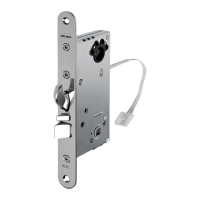
4. Install Levers
1. Insert outside mounting plate through door and lock body,
and hold (Figure 8).
2. Align and fasten inside mounting plate securely with two (2)
#8-32 x 1-1/4" screws.
3. Install roses on inside and outside adapter plates.
4. If included, press rose adapter into rose and mounting plate
assemblies.
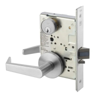
5. Unscrew inside spindle 1/2 turn and align ramp in the
horizontal position.
6. Slide plastic bushing onto outside lever and spindle and insert
through the lockbody.
7. Slide plastic bushing onto inside lever and attach to spindle.
Then tighten inside lever set screw.
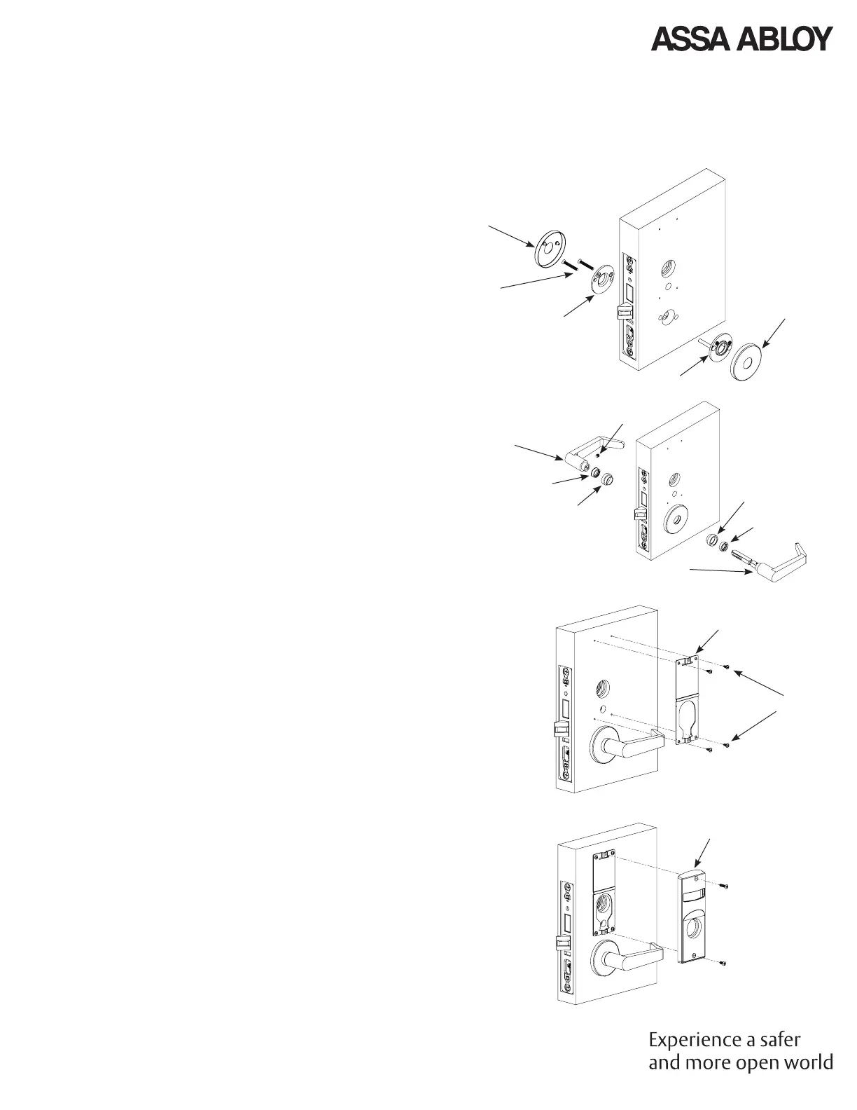
5. Installation, continued
5. Install Indicator Mounting Plate
1. Align and fasten inside mounting plate securely with two (2)
#8-32 x 1-1/4" screws.
2. If indicators are being used on both sides of door, repeat step
5.1 for opposite side.
6. Install Indicator Assembly
1. Verify lock is in unlocked state (turn outside lever to conrm).
2. Verify indicator is in vacant/unlocked position.
3. Assemble indicator assembly onto mounting plate (Figure 10).
4. Secure indicator assembly to door with two (2) machine
screws.
• Use #8-32 x 5/8" screw for top
• Use #8-32 x 3/8" screw for bottom
5. If indicators are being used on both sides of door, repeat steps
6.1 through 6.3 for opposite side.
NOTE: Torx security screws recommended.
Figure 8
Figure 9
Figure 10
Inside of
Door
Inside of Door
Outside of
Door
Outside of
Door
Rose
#8-32 x 1-1/4"
Screws
Inside
Mounting
Plate
Outside Mounting Plate
RH Door
Shown
Rose
Rose Adapter
Plastic Bushing
Rose Adapter
Plastic Bushing
Inside Lever
Set Screw
Outside Lever and Spindle
Mounting Plate
#6 x 3/8" Screws
#8-32 x 3/8"
Screw
#8-32 x 5/8"
Screw
Indicator
Assembly
 Loading...