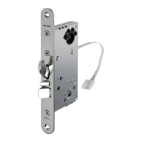
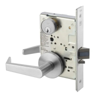
8800 Series Mortise Lock
Used with Sectional Trim and V Series Indicators
Installation Instructions
3
80-8800-0016-000 10/23
1-800-438-1951 • www.assaabloy.com
Copyright © 2020, 2023, ASSA ABLOY Access and Egress Hardware Group, Inc. All rights reserved. Reproduction in whole
or in part without the express written permission of ASSA ABLOY Access and Egress Hardware Group, Inc. is prohibited.
3. Lock Set Conguration
To re-hand lock, see instructions on lock body.
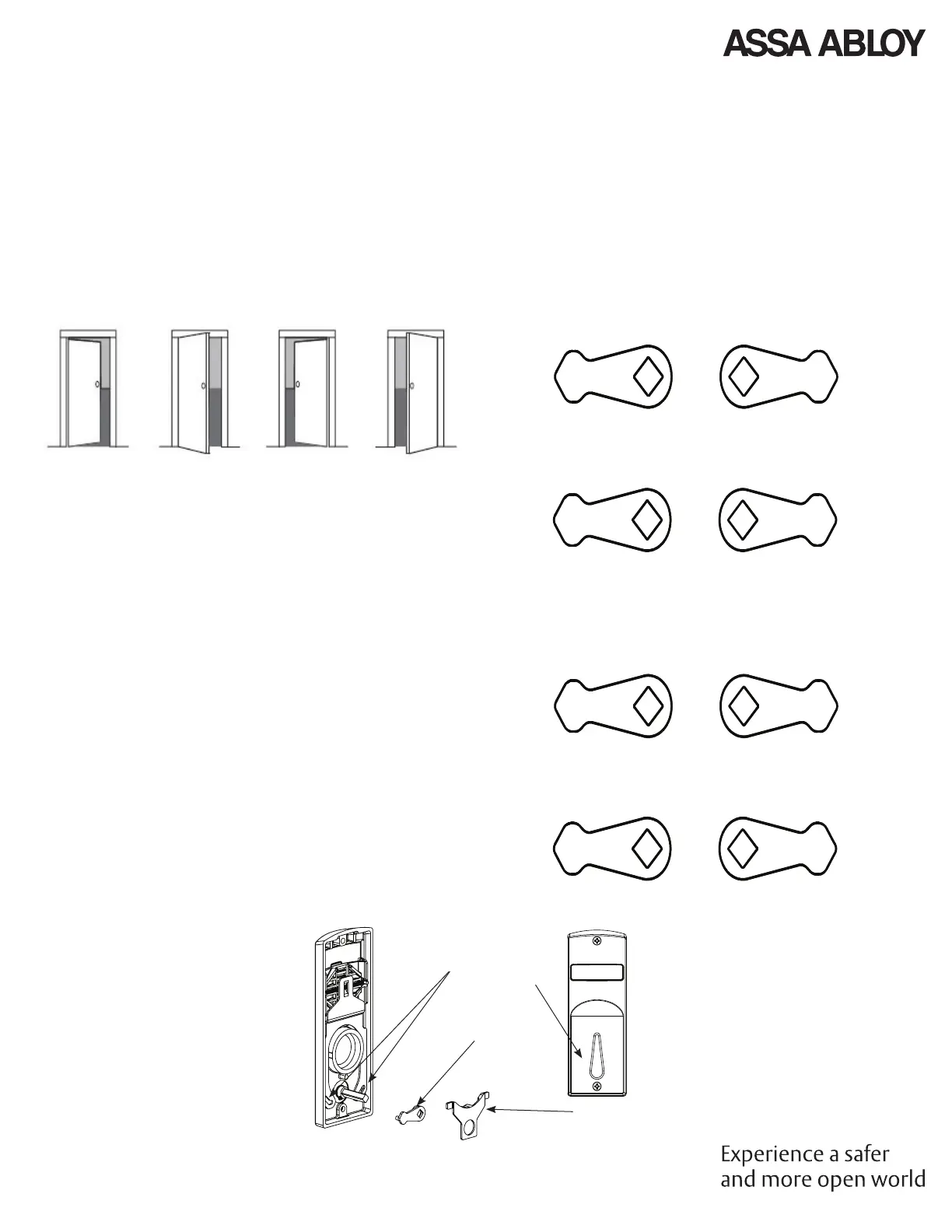
4. Rehanding Indicator (If required)
Verify hand and bevel of door (Figure 2).
Figure 2
LH
Left Hand
Hinges Left
Open Inward.
LHRB
Left Hand
Reverse Bevel
Hinges Left
Open Outward.
RH
Right Hand
Hinges Right
Open Inward.
RHRB
Right Hand
Reverse Bevel
Hinges Right
Open Outward.
NOTE: Stand on outside of locked door when determining door
hand.
Next, verify inside and/or outside indicators are handed correctly,
using Spindle Cam Position chart (Figure 3). If they are handed
correctly, skip to Step 5 “Prepare Door”.
If they are not handed correctly:
1. Remove retaining pad and spindle cam from assembly
(Figure 4).
2. Position spindle cam in correct direction for door hand
(Figure 3).
NOTE: For thumbturn indicators, make sure thumbturn is
positioned in the 12 o'clock direction as shown (Figure 5).
3. Slide spindle cam post into correct slot of display slide
(Figure 4).
4. Re-seat retaining pad into original position.
5. Rerurn indicator to the vacant/unlocked position for
installation.
Door Hand RH/RHRB
Figure 3
Spindle Cam Position for Locks with Deadbolt
(*Includes 8864 function)
Outside Indicator
Inside Indicator
Door Hand LH/LHRB
Inside Indicator
Outside Indicator
Spindle Cam Position for Locks without Deadbolt
(*Does not include 8864 function)
Door Hand RH/RHRB
Inside Indicator
Outside Indicator
Door Hand LH/LHRB
Outside Indicator
Inside Indicator
Display Slide
Slot
Spindle Cam
Retaining Pad
Thumbturn
Position
Figure 4
Figure 5
 Loading...