8800 Series Mortise Lock
Used with Sectional Trim and V Series Indicators
Installation Instructions
4
80-8800-0016-000 10/23
1-800-438-1951 • www.assaabloy.com
Copyright © 2020, 2023, ASSA ABLOY Access and Egress Hardware Group, Inc. All rights reserved. Reproduction in whole
or in part without the express written permission of ASSA ABLOY Access and Egress Hardware Group, Inc. is prohibited.
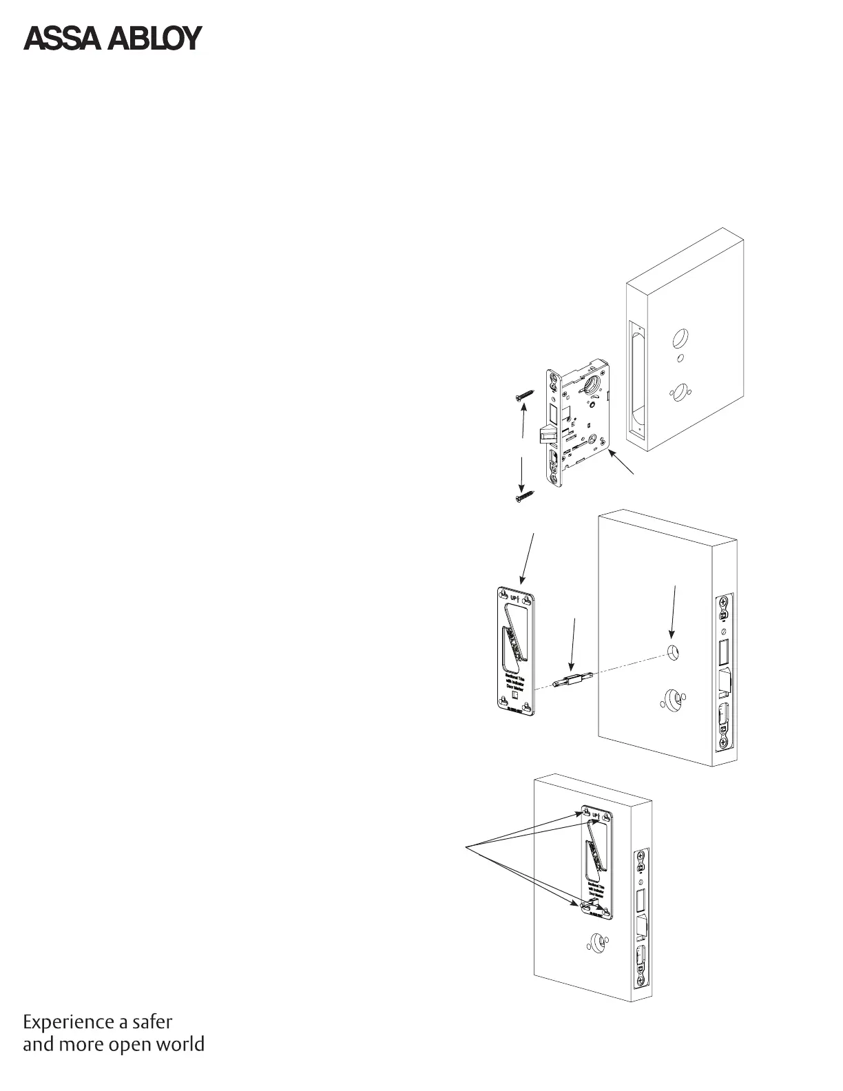
5. Installation
1. Prepare Door for Mortise Lock
Prepare door for function holes, size, and location according to
7088-0006 door marker template, if not already prepped.
2. Install Lock
1. Verify strike location according to template. Clean out door
pocket and door edge of debris.
2. Make sure handing of lock matches handing of door. Slide lock
into door (Figure 6).
3. Temporarily hand tighten two (2) lock screws (#12x1-1/4"
wood screws, or #12-24x1/2" machine screws).
NOTE: Keep door open until installation is complete.
3. Prepare Door for Indicator
1. Insert template guide into control hub on side where indicator
will be used (Figure 7).
2. Slide indicator template over template guide.
NOTE: Make sure the template is properly centered and aligned
to ensure smooth indicator operation.
3. Mark the four (4) hole positions indicated on template.
4. Remove guide and template.
5. If indicators are being used on both sides of door, repeat steps
3.1 through 3.4 for opposite side.
6. Remove lock body.
7. Drill four (4) marked holes with 3/32" diameter bit, by 1/2"
deep.
8. Reinstall lock body and hand tighten screws.
NOTE: If retrotting over an existing product, ensure door
surface is free of chips and debris around holes so indicator will
sit at against door surface.
Mark Holes
with Pencil
Template
Guide
Control Hub
Lock
Screws
Lock
Inside of
Door
Outside
of Door
RH Door
Shown
Figure 6
Figure 7
 Loading...