15
R
R
Copyright
©
Abloy Oy Joensuu Factory
1
2
3
4
5
6
1
2
3
4
5
6
1
2
3
1
2
3
1
2
3
4
5
6
1
2
3
4
5
6
WIRING DIAGRAM
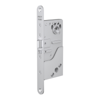
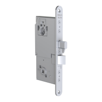
EL654, EL655
The connection to the network is accomplished by four wires, two
wires for the bus network and two wires for the power supply. Please
use CAN-cable ABLOY® EA216 (9 x 0.14 mm2) with the lock.
White
White - CAN High
EA216 (6m)/EA226
(10m) Connection Cable
Loop cut -> Auxiliary lock not connected
Loop uncut -> Auxiliary lock connected
Loop cut -> Group 1
Loop uncut -> Group 2
AUXILIARY LOCK CONNECTION CABLES
EA236: EL480, EL482, EL402
EA235: EL490
Brown
Brown - CAN Low
Green
Green - +12 - 27.6V DC STAB.
Yellow
Yellow - GND
Blue
Blue - Not in use
Black
Black - Common
Grey
Grey - Group
Red
+12 - 27.6V DC *)
Black
Relay output C
Yellow
Relay output NC
Blue
Bolt Out (input)
Green
Relay output NO
White GND
 Loading...