16
R
R
Copyright
©
Abloy Oy Joensuu Factory
1
2
3
4
5
6
1
2
3
4
5
6
1
2
3
1
2
3
1
2
3
4
5
6
1
2
3
4
5
6
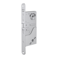
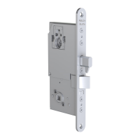
WIRING DIAGRAM
EA470 - EL654/EL655
Green and yellow wire from EA216 cable can be connected to pins 1 & 2 or 19 & 20.
- When connected to pins 1 & 2:
* Make sure that the polarity is correct and that the voltage is +12 - 27.6V (EL654).
* Do not use AC!
Green and yellow wire from EA216 cable can be connected to
pins 1 & 2 or 19 & 20.
- When connected to pins 19 & 20:
* Supply the one EL654/EL655 lock case only which, when needed, can
be connected to an auxiliary lock case EL480, EL482, EL402, EL490.
Otherwise please use pins 1 & 2.
* Power supply for lock case is 12V.
12-24 V DC +15%
12 V AC -10%/+50%, RMS
Green
White
White - CAN High
+12 - 27.6V DC
Cables for aux. locks
EA236: EL480,
EL482, EL402
EA235: EL490
Loop cut -> Group 1
Loop uncut -> Group 2
Loop cut -> Auxiliary lock not connected
Loop uncut -> Auxiliary lock connected
Red
Connection cable
ABLOY EA216
Yellow Brown
Blue
Brown - CAN Low
Relay output C
Black
Blue - Aux.lock
White
Green
Black
Green - +12 - 27.6V DC STAB.
Relay output NC
Yellow
Relay output NO
Green
Black C
Bro wn
Yellow
Grey
Yellow - GND
Bolt out (input)
Blue
GND
White
Grey - Group
Open
Open
Door
Double action bolt
Locked
Locked
Bolt in
Bolt out
Opening
Potential free control
Night/Day
Bus termination 120 ohms (Dip 1)
0: Resistor is not connected
1: Resistor is connected (default setting)
Delay (Dip 1-3)
Can be adjusted between 2 - 15 sec
Groups (Dip 4)
0: Lock case in group 1
1: Lock case in group 2
Delay clearance (Dip 4)
0: Delay is cleared by door sensor
1: Door sensor does not affect the delay
 Loading...