10
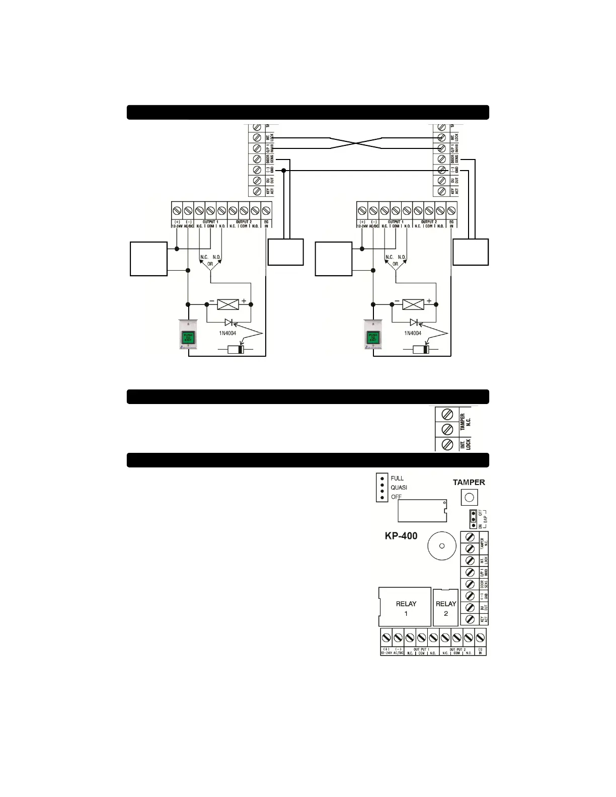
INTER-LOCK SYSTEM WIRING DIAGRAM
12 OR 24V
AC OR DC
POWER
SUPPLY
AC POWER
CAN ONLY BE USED
WITH
AC POWERED
ELECTRIC STRIKES
MAGNETIC LOCK
OR
ELECTRIC STRIKE
MODEL TS-2
REQUEST TO
EXIT STATION
(OPTIONAL)
USE N/O CONTACTS
+
-
N/C
DOOR
CONTACT
12 OR 24V
AC OR DC
POWER
SUPPLY
AC POWER
CAN ONLY BE USED
WITH
AC POWERED
ELECTRIC STRIKES
MAGNETIC LOCK
OR
ELECTRIC STRIKE
MODEL TS-2
REQUEST TO
EXIT STATION
(OPTIONAL)
USE N/O CONTACTS
+
-
N/C
DOOR
CONTACT
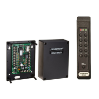
Two keypads are required for an inter-lock system. If either door is open, the other door
will remain locked.
TAMPER SWITCH
The Tamper Switch is Normally-closed when the keypad face plate is
securely attached to the back box. Connect these terminals to an alarm
panel if desired.
BACKLIGHT ADJUSTMENT
The keypad has an adjustable backlight feature. The
backlight illumination can be set to “FULL”, “QUASI”, and
“OFF” using the jumper located in the upper left hand corner
of the PCB assembly behind the front plate.
 Loading...