3
HANDING & ASSEMBLY OF D.S./DSHO SHOE
DO NOT BACK VALVES OUT OF
CLOSER OR A LEAK WILL RESULT
REGULATION
CAUTION
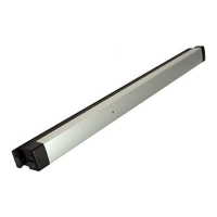
Both the DS and DSHO shoes must be "handed" to match door BEFORE
mounting. See Fig. 1
For Left Hand doors: All shoes are shipped assembled for left hand doors.
Insert 5/16" (8mm) hex wrench into arm stop and turn counter-clockwise to
seat stop as tightly as possible.
For Right Hand doors (see illustration): Push filler plug out of shoe. Using a
5/16" (8mm) hex wrench, turn arm stop clockwise to remove from shoe.
Thread arm stop in hole marked "R". Turn wrench counter-clockwise, seating
stop as tightly as possible. Insert filler plug into other hole.
1. Adjust spring power to match door width as indicated by chart on front page.
2. Select proper templating on opposite page, based on degree of
opening/dead stop. The closer and arm holes must be located for same
degree of opening/dead stop. Drill and/or tap mounting holes in door and
head jamb.
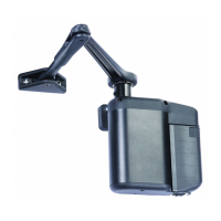
3. Attach complete arm to closer, as shown at left. Arm will be at about a 30°
angle to closer body. Fasten with arm shaft screw. The arm will appear to be
in an incorrect position. This is to accommodate the pre-load required for
parallel arm mounted door closers. See Fig. 2.
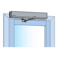
4. Mount closer on door, using fasteners provided. NOTE: Arm will provide
some resistance.
5. Swing door open about 45°. Mount shoe to frame stop per proper templating
on opposite page. Be sure to install the "fifth" screw. If stop is not wide
enough, use spacer block provided.
Closer has been regulated prior to shipment. If adjustments are necessary,
carefully follow instructions.
CLOSING SPEED: See Closer Control Diagram on page 1. To adjust Main
Speed, turn reg. screw clockwise to decrease or counter-clockwise to increase.
To adjust Latch Speed, turn reg. screw clockwise to decrease or counter-
clockwise to increase. Reg. Screw locations are shown at left and on label.
BACKCHECK: is essential for proper operation of built-in stop. Use enough
backcheck to prevent arm from striking arm stop with impact. To increase
resistance, turn reg. screw clockwise. DO NOT USE ABRUPT BACKCHECK!
6. Attach cover: Place cover insert into proper slots for either R.H. or L.H. door.
Place cover over closer and hold against door while tightening cover screws
firmly.
BA-DC500 with DSHO Arm Rev A 8/10
Arm
Screw
Screw
Main Speed
Backcheck Screw
Hand Cover
Screw
Latch Speed
Main Arm
Selector Valve Screw
Removable Inserts
To Convert To Opposite
30°
Approx
Cover
Screw
Main Arm
Optional
Drop Plate
5/16" 0R 8 mm
Hex Wrench
Arm Stop
Filler Plug
IMPROPER INSTALLATION OR
REGULATION MAY RESULT IN
PERSONAL INJURY OR PROPERTY
DAMAGE.
FOLLOW ALL INSTRUCTIONS CAREFULLY.
FOR QUESTIONS CONTACT DEALER
CAUTION
INSTALLATION & ADJUSTMENT INSTRUCTIONS
RIGHT HAND ASSEMBLY SHOWN
Fig.2
Fig.1
(LEFT HAND SHOWN - RIGHT HAND OPPOSITE)
BEFORE INSTALLING THE ARM - TURN BACKCHECK
SELECTOR VALVE (on back of closer) ALL THE WAY IN.
Size Adjust
 Loading...