EasyManua.ls Logo

Assa Abloy ACCENTRA 6000 Series - User Manual

Assa Abloy ACCENTRA 6000 Series
24 pages
Print Icon
To Next Page IconTo Next Page
Loading...
6000 Series Motorized
Electric Latch Retraction (MELR)
Exit Devices
Installation Instructions with Optional “S” Bolt Monitor, “B”
Touchbar Monitor, and “O” Trim Monitor Connection
Attention Installer: Any retro t or other eld modi cation to a re rated opening can potentially impact the re rating of the
opening, and ASSA ABLOY makes no representations or warranties concerning what such impact may be in any speci c
situation. When retro tting any portion of an existing re-rated opening, or specifying and installing a new re-rated opening,
please consult with a code specialist or local code o cial (Authority Having Jurisdiction) to ensure compliance with all appli-
cable codes and ratings.
WARNING
80-8150-0077-000 04/24
1-855-557-5078 Ext. 2 • www.accentra-assaabloy.com
Copyright © 2017, 2023, 2024, ASSA ABLOY ACCENTRA™ Access and Egress Hardware Group, Inc. All rights reserved. Reproduction in
whole or in part without the express written permission of ASSA ABLOY Access and Egress Hardware Group, Inc. is prohibited.
WARNING
This product can expose you to lead which is known to the state of California to cause cancer and birth defects or other
reproductive harm. For more information go to www.P65warnings.ca.gov.
Question and Answer IconNeed help?

Do you have a question about the Assa Abloy ACCENTRA 6000 Series and is the answer not in the manual?

Overview

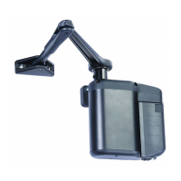
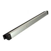
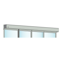
The 6000 Series Motorized Electric Latch Retraction (MELR) Exit Device is a commercial-grade solution designed to provide remote-controlled latch retraction for various 6000 series exit devices (including 6100, 6130, 6150, 6160, 6170, 6200, 6210, 6250, and 6220). This system offers enhanced security and convenience through its electrical control capabilities and compatibility with several monitoring options. The MELR option is also compatible with hex key, cylinder key, and fire-rated mechanical configurations, offering flexibility in application.

Function Description

The MELR option can be configured to operate in two distinct modes:

  • Power Mode: In this mode, the device is not energized when locked. When a 24V power input is applied, the pushbar and latch(es) retract and remain in the retracted position until power is removed. Power is typically supplied via a relay triggered by an access control device. This mode is suitable for applications where the device needs to be unlocked for a specific period and then relocked upon power removal. The rail retracts when power is applied and releases when power is removed.
  • Timer Mode: In this configuration, the device is continuously energized with a 24V input. Latch retraction is triggered by closing a timer circuit using either a momentary or maintain switch.
    • Momentary Switch: When the timer circuit is closed momentarily, the device retracts, remains retracted for a set duration, and then releases. The retraction duration can be adjusted using an onboard timer setting, ranging from 0 to 20 seconds.
    • Maintain Switch: When the timer circuit is closed using a maintain switch, the device retracts and remains retracted as long as the contact is closed. The device releases when the contact is opened.
    • For delays exceeding 20 seconds, an external timer delay relay (not provided) is required.

Optional Monitoring Features:

The MELR system integrates with several optional monitoring switches to provide comprehensive status feedback:

  • "S" Latchbolt Position Monitor: This feature provides an indication of the latch bolt's position. It is used with security systems to monitor the latch bolt's status and can activate automatic door operators upon latch retraction. The "S" NO/NC (Normally Open/Normally Closed) contact is selectable on the controller via DIP switch settings, with a factory preset of NO.
  • "B" Touchbar Monitor: This monitor indicates when the pushbar is depressed. It serves as a request-to-exit signal to shunt alarm systems, release electromagnetic locks, or monitor egress.
  • "O" Trim Monitor Switch: This switch indicates when the device is operated from the outside. It functions as a request-to-enter signal switch to shunt alarms and monitors entry. The "O" NO/NC (Normally Open/Normally Closed) output is selectable on the controller, with a factory preset of NO.

Important Technical Specifications

  • Voltage: 24VDC
  • Power Supply: Requires a filtered and regulated power supply.
  • Motor Operating Current: 800mA
  • Motor Hold Current: 330mA
  • Contact Ratings:
    • "S" Latch Bolt: 200mA@28VDC
    • "B" Touch Bar: 1A@30VDC
    • "O" Trim: 1A@28VDC
  • Wire Gauge Chart: Provides guidance for appropriate wire gauges based on total one-way wire run length and load current at 24VDC, ranging from 1/4A to 3A. For MELR, 1A is the recommended current draw for voltage drop calculations.
  • Hinge Requirements: The number of wires required varies based on the MELR configuration and whether the timer mode is used. For example, a basic MELR without a timer requires 3 wires and a QC8 hinge, while a "S", "B", "O" MELR with a timer requires 12 wires and a QC12 hinge.
  • ElectroLynx Wiring System: Devices are supplied with 4-pin and 8-pin Molex® connectors for simple installation using the ASSA ABLOY ElectroLynx® system. This system ensures proper connections and reduces installation complexity. Do not force connectors, as they plug and lock in only one way.
  • Earth Ground: Required for electrostatic discharge (ESD) protection unless the metal door and frame are already earth grounded. If not, earth ground wiring is required at pin 4.

Usage Features

  • DIP (Dual Inline Package) Switch Settings: The controller features DIP switches for configuring various operational parameters.
    • Switches #1 and #2 control the LBM (Latch Bolt Monitor) contact type (Normally Closed or Normally Open). Only one of these should be closed at a time.
    • Switch #3 enables Power Mode (bypassing external trigger) when closed.
    • Switches #4, #5, and #6 select software options, allowing up to 8 Time/Delay settings for Timer Mode.
    • Default setting: LBM/NO and Power Mode set to ON.
  • LED Signaling: An onboard LED provides visual feedback on the device's status:
    • Dark / Unlit: Controller microprocessor is not active. Troubleshooting: Confirm connections and incoming power.
    • Steady Flashing: Normal operation. Troubleshooting: Check that Power Mode switch is set (for Power Mode) or cycle device by closing timer circuit (for Timer Mode).
    • Solid Light: Input voltage is dropping out of operation range. Troubleshooting: Check wire run and power supply output.
    • 2 Flashes Followed by Pause: Retractor sensor problem. Troubleshooting: Call technical support.

Maintenance Features

  • Troubleshooting Guide: The manual provides detailed troubleshooting steps for both Power Mode and Timer Mode, addressing common issues such as the pushbar not moving, incomplete retraction, failure to relock, abnormal rail behavior, and operator timing problems.
  • Mechanical Function Verification: Before electrical troubleshooting, installers must confirm proper mechanical function, ensuring the pushbar fully depresses, latches fully retract, and the door opens freely.
  • Disconnection Warning: Always disconnect power before making any mechanical adjustments to the system.
  • Technical Support: A dedicated technical product support line (1-855-557-5078 Ext. 2) is available for assistance. When calling, providing information such as contact details, product type, location, order number, power supply specifications, operation method, number of devices, and observed symptoms can help improve service.
  • Wiring Recommendations: For non-ElectroLynx installations, Molex connectors with flying leads can be purchased separately, or the ElectroLynx connector can be removed, and wires can be nutted to the electric hinge wires, with color coordination recommended.
  • Wire Management: Excess wiring should be stored under the end cap, and care must be taken to avoid pinching wires during assembly.
  • Installer Expertise: Installation must be performed by a trained and experienced service person, and wiring must comply with applicable local electrical codes, ordinances, and regulations.
  • Fire-Rated Door Restrictions: Hex key or cylinder (6XX5) mechanical dogging CANNOT be used on Fire Rated Doors.
  • Fire Rating Impact: Any retrofit or field modification to a fire-rated opening can potentially impact its fire rating. Installers are advised to consult with a code specialist or local code official to ensure compliance with all applicable codes and ratings.
  • Product Warnings: The product contains lead, which is known to cause cancer and birth defects or other reproductive harm (refer to www.P65warnings.ca.gov for more information).

Assa Abloy ACCENTRA 6000 Series Specifications

General IconGeneral
BrandAssa Abloy
ModelACCENTRA 6000 Series
CategoryDoor Opening System
LanguageEnglish

Related product manuals