EasyManua.ls Logo

Assa Abloy Lockwood Onyx 9A1A2/5PBLK User Manual

Assa Abloy Lockwood Onyx 9A1A2/5PBLK
2 pages
To Next Page IconTo Next Page
Page #1 background imageLoading...
Page #1 background image
Application: Provides safe latching or secure deadlocking for sliding
aluminium and timber doors.
Operation: Snib to latch, key to deadlock.
077278 - June14
• Several chassis fixing screws are
provided to suit different door
thicknesses
Screws are a “taptite” screw that makes
its own thread – therefore the outer
pulls are not pre threaded
Use the table to identify
which are the correct
length fixing screws for
your application
4. Screw Selection
Door Thickness Screw Selection
19-29mm M4 x 50mm
30-39mm M4 x 60mm
40-49mm M4 x 70mm
Template
75 75
62.5 62.5
LINE 1
BACK WALL OF JAMB
FIXED DOOR FRAME FRONT EDGE
LINE 2
11
16
33
4141
ø3
ø10
Tools Required:
• Drill • Phillips Screwdriver ø10mm Drill Bit
ø3mm Drill Bit • Hacksaw or cutters • Rule and pencil or marker
Installation Instructions
• Place the cylinder with tail in the outer
pull and place cylinder retainer over
the back of the cylinder as shown
3. Cylinder Preparation
Surface Fix (Follow holes labelled A)
• Ensure door is closed correctly. Place
template on the inside surface of the jamb
(fixed door frame) at the desired height
If ‘X’ is greater than 19mm, align ‘LINE 1’
with the outer edge
If ‘X’ is less than 19mm align ‘LINE 2’
against the back wall
Mark and drill all holes marked ‘A’
(3x
ø10mm, 2xø3mm)
For 3x
ø10mm holes - do not fold
template over outer edge step
1. Door Preparation
Note: If the Flat Outer Pull option is being fitted, drill centre hole ø4mm and refer to step 9.
• Remove components from packaging.
If beaks are in the locked position shown,
push the snib button down to retract
the beaks
Press in the DCD (door closed detect)
button and remove the lock chassis from
inside the D-Handle body
2. Lock Chassis and Handle Preparation
Press in
DCD Button
Locked
Position
Snib Button
Outer Edge
Back Wall
D-Handle
Cylinder
Wedge
Cylinder
28mm Screws
Chassis
Fixing Screws
Lock Chassis
Cylinder Retainer
Cylinder with Tail
Outer Pull Strike Body
Strike Cover
7mm Screws
16mm Fixing
Screws
Pack Contents
• Place the outer pull on the external face of
the door with the tail passing through the
centre hole
• Mark and cut the cylinder tail piece 10-
12mm past the door (allow an extra 5mm
if a handle packer is to be fitted)
Side Fix (Follow holes labelled B)
• Fold template 90° along ‘LINE 1’
Ensure door is closed correctly. Place
template against the door surface at
the desired height
Mark and drill all holes marked ‘B’
(3x
ø10mm, 2xø3mm)
10-12mm
Sliding Door Lock
A
A
A
B
B
B
X
Question and Answer IconNeed help?

Do you have a question about the Assa Abloy Lockwood Onyx 9A1A2/5PBLK and is the answer not in the manual?

Assa Abloy Lockwood Onyx 9A1A2/5PBLK Specifications

General IconGeneral
BrandAssa Abloy
ModelLockwood Onyx 9A1A2/5PBLK
CategoryDoor locks
LanguageEnglish

Summary

Sliding Door Lock Installation

Pack Contents

Lists all components included in the lock package for verification.

Door Preparation

Details the process of preparing the door for lock installation, including drilling.

Surface Fix Door Prep

Instructions for fixing the lock to the door surface using template holes.

Side Fix Door Prep

Instructions for fixing the lock to the door edge using template holes.

Lock Chassis and Handle Preparation

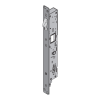
Describes preparing the lock chassis and handle by removing components.

Cylinder Preparation

Details the steps for preparing and fitting the cylinder to the outer pull.

Screw Selection

Guides on selecting appropriate screws based on door thickness for secure fitting.

Fixing Outer Pull and Lock Chassis

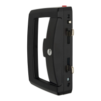
Instructions for attaching the outer pull and lock chassis to the door.

Fixing Inner Handle

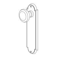
Details the process of installing the inner handle onto the lock chassis.

Strike Installation

Provides instructions for installing the strike plate on the door jamb for proper engagement.

Surface Fix Strike

Steps for fixing the strike body and cover to the jamb surface.

Side Fix Strike

Steps for fixing the strike assembly to the door edge.

Check Lock Operation

Explains how to test the lock's latching and deadlocking functions for security.

Fixing Flat Outer Pull

Instructions for fitting an optional flat outer pull as an alternative.

6-pin Cylinder Assembly

Details the installation process for a 6-pin cylinder.

Related product manuals