Do you have a question about the Assa Abloy Sargent IN220 and is the answer not in the manual?
Explains compliance with FCC rules for digital devices and radio frequency energy.
Details compliance with Canadian Interference Causing Equipment Regulations.
Basic precautions for handling electronic components to avoid electrostatic discharge.
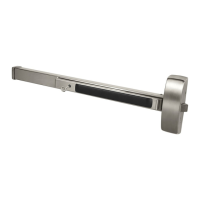
Lists hardware features for the IN220 PoE Rim Exit.
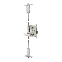
Lists hardware features for the IN220 PoE Mortise Exit.
Lists part numbers and descriptions for the Rim Exit device.
Lists part numbers and descriptions for the Mortise Exit device.
Illustrates a typical SARGENT IN220 PoE application and its components.
Details the installation and wiring of the PoE frame harness.
Covers hinge installation and routing of the PoE door harness.
Steps for preparing the door, including checking hand, bevel, and prep work.
Instructions for installing the Door Position Switch (DPS).
Steps for mounting the exit device chassis.
Details connecting the motor harness and mounting the ET trim.
Steps for installing the cylinder.
Instructions for fastening the exit chassis to the door.
Steps for securing the chassis cover.
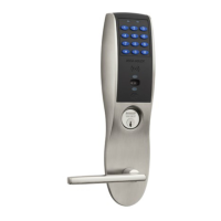
Steps for installing the outside reader and mounting plate.
Further steps for reader installation, including cables and ground lugs.
Instructions for connecting various components and crimping cables.
Details installing the inside components and removing the coin cell pull tab.
Steps for assembling and securing the inside cover.
Instructions for installing the rail assembly.
Steps for preparing the door for mortise installation.
Instructions for installing the Door Position Switch (DPS).
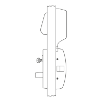
Steps for mounting the mortise lock and chassis.
Details routing wires and mounting the ET trim for mortise devices.
Steps for installing the cylinder for mortise devices.
Instructions for fastening the exit chassis for mortise devices.
Steps for securing the chassis cover for mortise devices.
Steps for installing the outside reader and mounting plate for mortise devices.
Further steps for reader installation, including cables and ground lugs.
Instructions for connecting components and crimping cables for mortise devices.
Details installing inside components and removing the coin cell pull tab.
Checks to perform on the cylinder, including key operation and free rotation.
Interpreting LED signals and checking input voltage and power conditions.
| Brand | Assa Abloy |
|---|---|
| Model | Sargent IN220 |
| Category | Door locks |
| Language | English |