Do you have a question about the Assa Abloy SARGENT IN120 Wi-Fi Series and is the answer not in the manual?
| Brand | Assa Abloy |
|---|---|
| Model | SARGENT IN120 Wi-Fi Series |
| Category | Door locks |
| Language | English |
Details FCC rules for digital devices and potential interference.
Outlines Industry Canada regulations for radio transmitters.
Covers FCC and IC compliance for license-exempt transmitters/receivers.
Warns about lead exposure and reproductive harm.
Advice on retrofitting fire-rated openings and consulting code officials.
Basic precautions for handling electronic components to prevent ESD damage.
Details specifications for mobile credential-enabled lock versions.
Lists UL 294 ratings for the device (Destructive Attack, Line Security, etc.).
Details power requirements for IN120 (Wi-Fi) and IN220 (PoE) versions.
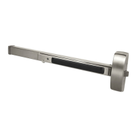
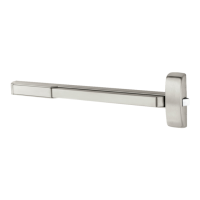
Lists hardware specifications for the IN120/220 PoE Rim Exit device.
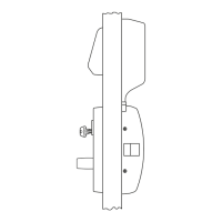
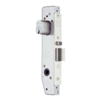
Lists hardware specifications for the IN120/220 PoE Mortise Exit device.
Lists supported high-frequency credentials like HID iCLASS, MIFARE.
Lists supported low-frequency credentials like HID Prox.
Details mobile phone credential support (Apple Wallet, HID Mobile Access).
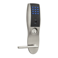
Details features like PIN usage, scheduling, audit trail, privacy button.
Lists power options (batteries, PoE, hard power).
Lists necessary tools for installation.
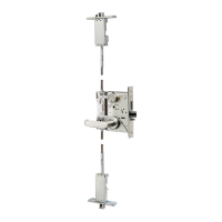
Lists components with item numbers and descriptions for the main unit.
Provides a high-level overview of the PoE system setup.
Lists components of the EAC Software System (harnesses, lock, DPS).
Important notes about connecting components correctly.
Details wiring standards and preparation for the ceiling-side harness.
Instructions for feeding and connecting the frame-side harness.
Identifies connectors for the PoE data hinge and lock-side.
Lists connector types for PoE door harness hinge and lock sides.
Steps for routing the PoE harness to the lock.
Steps for preparing the door for installation.
Instructions for installing the Door Position Switch (DPS).
Instructions for mounting the exit device chassis.
Steps for mounting the exit trim (ET).
Instructions for installing the cylinder.
Instructions for securing the exit chassis to the door.
Steps to install the chassis cover.
Steps for preparing the door for mortise installation.
Instructions for installing the Door Position Switch (DPS).
Steps for mounting the mortise chassis.
Steps for positioning the exit trim (ET).
Instructions for installing the cylinder.
Instructions for securing the exit chassis.
Steps to install the chassis cover.
Steps for installing the outside reader and mounting plate.
Continues steps for reader/mounting plate installation.
Instructions for installing various connectors with grease.
Details Ethernet cable preparation for PoE.
Instructions for installing the controller.
Continues steps for controller installation.
Instructions for supplying power to the controller (PoE).
Instructions for installing batteries for the IN120 Wi-Fi version.
Steps for installing the inside cover.
Checks if the inside exit bar correctly retracts the latch.
Procedures for testing the cylinder function.
Procedures for testing with keypad and card credentials.
Explains the meaning of different LED signals.
Describes behavior when the lock loses power.