EasyManua.ls Logo

Assa Abloy Sargent 10X Line User Manual

Assa Abloy Sargent 10X Line
4 pages
To Next Page IconTo Next Page
Page #1 background imageLoading...
Page #1 background image
A8334 07/22
Installation Instructions
For installation assistance contact SARGENT
1-800-543-3658 • techsupport.sargent@assaabloy.com • www.sargentlock.com
Copyright © 2022, ASSA ABLOY Access and Egress Hardware Group, Inc. All rights reserved.
Reproduction in whole or in part without the express written permission of ASSA ABLOY Access
and Egress Hardware Group, Inc. is prohibited.
2
11
3
4
5
6
8
7
9
1
14
12
13
15
10
Installation Instructions
2
Product Components
1
Tools Required
10X Line with BHW Trim
Fig. Description
1 Inside escutcheon & lever assembly
2
Outside escutcheon & lever
assembly
3 Inside spring housing assembly
4
Screws - through-bolt (2) #10-32
x 1-1/4"
5
Lockbody assembly with mounting
plate
6 Outside spring housing assembly
7 Cylinder spacer
8 Cylinder
9 Key
10 Latch
11 Screws - latch (2) #8-32 x 3/4"
12 Screws - strike (2) #12-24 x 3/4"
13 Strike
14 Strike box (Optional)
15
Screws- through-bolt (3) #10-24 x
3-1/2"
3
Door Preparation
IMPORTANT
The accuracy of door preparation is critical for proper functioning and security of this lever handle lock. Misalignment can
cause premature wear and a lessening of security.
Be sure to verify backset before marking and drilling door.
1. Use template A8335 to mark the door (Figure 1).
2. Drill the door according to the template.
3. Verify the dimensions (Figure 2).
4. Install the strike (Figure 3)
DOOR
FRAME
Desired
height
above
floor
Template
Backset must
match latch
Door bevel
2x 7/16" (11mm) hole
1-1/8"
(29mm)
2-1/4"
(57mm)
1" (25mm)
hole
5/32" (4mm)
2-3/4"
(70mm)
Strike Box
Attaching Screws
#12 -24 x 3/4"
3x 1/2" (13mm) hole
4-3/4"
(120mm)
1-11/16"
(43mm)
2-1/8"
(54mm)
hole
5/8"
(16mm)
5/32" drill bit 1/2" drill bit 7/16" drill bit 1/8" drill bit
#2 Phillips screwdriver T25 Security Torx
®
screwdriver T15 Security Torx
®
screwdriver
Question and Answer IconNeed help?

Do you have a question about the Assa Abloy Sargent 10X Line and is the answer not in the manual?

Assa Abloy Sargent 10X Line Specifications

General IconGeneral
CategoryDoor locks
TypeMortise Lock
ANSI/BHMA GradeGrade 1
WarrantyLimited Lifetime
ModelSargent 10X Line
Backset2-3/4"
HandingReversible
SecurityHigh security
Door Thickness1-3/4" to 2-1/4"
FinishMultiple options available

Summary

Tools Required for Installation

Product Components Identification

Door Preparation and Verification

Figure 1: Door Marking with Template

Use template to mark door for drilling and backset verification.

Figure 2: Dimension Verification for Drilling

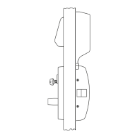
Verify door preparation dimensions against Figure 2 for accuracy.

Figure 3: Strike Plate Installation

Install the strike according to Figure 3, ensuring correct alignment.

Important Door Preparation Notes

Door preparation accuracy is critical for lock function and security.

Latch Installation Procedure

Figure 4: Latch Placement and Screws

Insert latch into door, ensuring bevel faces strike plate and secure.

Deadlocking Latch Functionality

Ensure deadlocking latch stops on strike when door is closed.

Door Thickness Adjustment

Figure 5: Retractor Flush Adjustment

Adjust mounting plate for door thickness, ensuring surfaces are flush.

Figure 6: Dimension A for Thickness

Verify correct position using markings or measure Dimension A.

Install Outside Lockbody Assembly

Figure 7: Lockbody Insertion

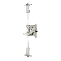
Insert lockbody, ensuring hooks engage latch case and retractor engages tail.

Latch Bolt Tail Centering

Center latch bolt tail in retractor depth, adjust if necessary.

Cylinder Installation

Standard Cylinder Installation

Rotate cam, install spacer, then insert cylinder into lever.

Interchangeable or Removable Core

Remove construction core, insert permanent core with control key.

Tailpiece and Core Important Notes

Manage tailpiece from construction core and for XC LFIC cores.

Install Escutcheon and Lever Assemblies

Figure 10: Securing Assemblies

Align and secure inside/outside escutcheons with spring housing using screws.

Cylinder Options for Lever

Figure 11: Competitor Cylinder Adaptation

Adapt competitor cylinder by modifying tailpiece and end cap.

Related product manuals