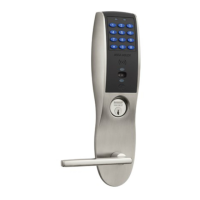
10X Line with BHW Trim
Installation Instructions
2
Copyright © 2022, ASSA ABLOY Access and Egress Hardware Group, Inc. All rights reserved. Reproduction in whole or in
part without the express written permission of ASSA ABLOY Access and Egress Hardware Group, Inc. is prohibited.
For installation assistance contact SARGENT
1-800-543-3658 • techsupport.sargent@assaabloy.com • www.sargentlock.com
A8334 07/22
Centerline
of retractor
Retractor
Dimension A
5
Door Thickness Adjustment (if necessary)
6
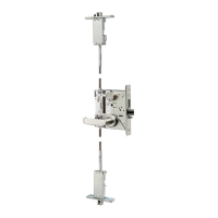
Install Outside Lockbody Assembly
To adjust lock to door thickness if other than 1-3/4"
(44mm) refer to Section 5.
Insert lockbody assembly into door from outside
making sure that lockbody hooks latch case and
retractor engages bolt tail(s). (Figure 7)
DO NOT FORCE. (If lockbody does not engage latch
easily, check door preparation for errors.)
Latch bolt tail should be centered in depth of
retractor. If it is not, refer to Section 5 to properly
adjust the lock for door thickness.
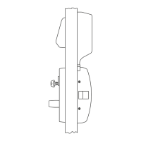
Lock is factory preset for 1-3/4" (44mm) doors unless specified. To adjust lock to
door thickness if other than 1-3/4" (44mm):
1. Remove outside spring housing from lockbody assembly.
2. Rotate mounting plate to adjust for proper door thickness.
• For 2" thick door the inside face of the mounting plate should be
flush with the face of the bearing. (Figure 5)
• Verify correct position from the markings on the through-bolt
stud, or by measuring from inside surface of the mounting plate to
the centerline of the retractor. (Figure 6)
3. Reassemble outside
spring housing onto
lockbody assembly.
Door Thickness Dimension A
1-3/4" (44 mm) 7/8" (22 mm)
2" (50 mm) 1" (25 mm)
4
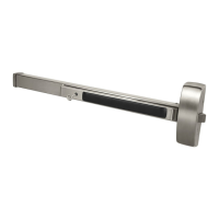
Latch Installation
Insert latch in door. (Be sure bevel edge of bolt faces strike plate.)
Attach with (2) #8-32 x 3/4" screws supplied.
Strike
Important: Deadlocking latch must stop on strike when door is closed.
Bearing
These
surfaces
flush
Mounting Plate
Figure 6Figure 5
 Loading...