1 of 8
Securitron
®
M32 | M62 | M82
Magnalocks
Installation & Operating Instructions
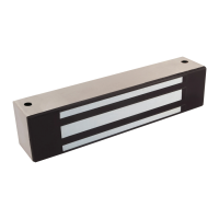
Product Components
A Magnalock
B Sex Bolt
C Roll Pins (2x)
D Strike Plate
E Funnel Bushing
F Roll Pin
Bushings (2x)
G 5/16-18 Screw
H Rubber Washers
I Magnalock
Installation
Template
Recommended Tools
• Power Drill
• Hammer
• Wire Strippers/
Cutter
• 1/8", 3/8", 1/2"
Drill Bits
• Center Punch
• Crimp Wire
Connectors
• Masking Tape
• Crimp Tool
• 3/16" Hex Key
(Allen Wrench)
• Fish Tape or
Lead Wire
• Multimeter
• 1/2" Open end or
Crescent Wrench
Introduction
The Securitron Magnalock
®
family is state of the art in electromagnetic
locking, and includes operational electrical characteristics and
mounting configuration options addressed in this document.
The BondSTAT “B” Magnalock Series, Bond Sensor, monitors the magnetic
field. An internal sensor activates a single pole double throw (SPDT)
dry-contact relay connection designed for interface with access control
and/or alarm systems, which reports the status of the Magnalock.
The DPS “D” Magnalock Series, Door Position Sensor, is activated by a
special magnetic strike armature assembly. This isolated SPDT reed switch,
with an internal resettable protection device, is designed to interface
with an access control and/or alarm system to monitor door status.
Diagram 1 Product
Components
A
C
D
E F G H
I
B
Specifications
M32 M62 M82
Holding Force 600 lbs [272 kg] 1200 lbs [544 kg] 1800 lbs [816 kg]
Length 8" [203 mm] 8" [203 mm] 12" [305 mm]
Height 1.88" [48 mm] 3" [76 mm] 3" [76 mm]
Depth 1.6" [41 mm] 1.75" [44 mm] 1.75" [44 mm]
Current at 12 VDC 300 mA 250 mA 350 mA
Current at 24 VDC 150 mA 150 mA 200 mA
Capacitance at 12 VDC 6.8 mF 44 mF 44 mF
Capacitance at 24 VDC 6.8 mF 11 mF 11 mF
Dual Voltage 12/24 Volts DC
BondSTAT Rating (voltage) 30 VDC (Maximum) ~ Current 1 Amp (Maximum)
DPS Rating (voltage) 30 VDC (Maximum) ~ Current 125 mA (Maximum)
Instructions NOTE: See installati on instruc tions for full inf ormation and t roubleshoot ing.
1. The relationship bet ween the two magne t
mounting hole s is critical. DO NOT let
your marking or dr illing wander.
2. DO NOT over drill the dia meter of the 3/8" [9.5 mm]
magnet mount ing holes or the blind nuts wil l
not seat. It is best to us e a center punch to
create indent ations for all drill locat ions.
3. Make sure the bl ind nuts are collapsed.
4. DO NOT over tighten t he magnet mounting
screws. Use pr ovided LOCTITE on sc rew threads.
5. Be care not to scr ape the magnet cable
when pushing it bac k into the frame.
6. The two r ubber washers sta ck one on top of the
other and mount in bet ween the strike and t he
door around the cent er strike mounting scre w.
DO NOT place the washer s on the roll pins.
7. When inser ting the sex bolt fro m the outside of
the door, DO NOT insert i t fully until you have
start ed the mating screw from t he other side.
This insures th at the sex bolt will go in straig ht.
8. DO NOT over tighte n the strike
mounting scre w into the sex bolt.
9. Make sure th e strike plate float s and pivots around
the center mounti ng screw. This compensate s
for door misalig nment. If the strike is mo unted
rigidly, the Mag nalock will NOT hold.
10. Use of roll pin plastic bush ings is recommended for
metal door s. It the plastic bushing s are not used, drill
3/8" [9.5 mm] diameter holes for the str ike roll pins.
Securitron
®
M32 Series Magnalock (Standard Mount)
Installation Template
Patent pe nding and/or p atent ww w.assaab loydss.co m/patents Copyrig ht © 2020, Hanche tt Entr y Systems ,
Inc., an A SSA ABLOY Grou p company. All r ights re served. Reproduc tion in who le or in par t without t he
expres s writte n permissi on of Hanche tt Entr y Systems , Inc. is pro hibited. 5 00-10850_7
WARNING DO NOT DRIL L into
magnet or st rike for any reaso n.
DO NOT photo copy te mplate.
(Dimensions wil l change)
CUT ALONG THIS LINE
Magnet
Strike Plate
CUT ALONG THIS LINE
FOLD ALONG THIS LINE
.4"
[10.2 mm]
.4"
[10.2 mm]
6.25"
[158.8mm]
7.2"
[182.9mm]
2.25"
[57.2 mm]
.813"
[20.7 mm]
.812"
[20.7 mm]
2.25"
[57.2 mm]
.875"
[22.2 mm]
.6"
[15.2 mm]
.6"
[15.2 mm]
2 X Screw Monting Holes:
· Blind nuts used: 3/8" [9.15mm] DIA.
· No blind nuts used: 3/16" [4.18mm] DIA.
Position edge of magnet 1/2" [12.7mm] from frame corner
to provide drilling clearance
3/8" [9.5mm] DIA. wire way hole
2 X 1/2" [12.7mm]
1" [25.4mm]
Deep into Door
3/8" [9.5mm] DIA. Through Door
1/2" [12/7m m] DIA. from other
side for sex bolt
Vertical Mount: Move strike holes 1/10 " [2.5 mm] further from fold line.
Offset Strike: Move strike holes 1/4" [6.4 mm] towards fold line
Header
Door