3 of 8
DOOR
FRAME
TOP OF
DOOR FRAME
DOOR
1
A – C/D Drill holes
3
2
Attach the Template and
Mark the Drill Holes
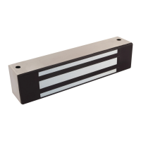
1 SELECT a mounting location for the
Magnalock and strike assembly.
NOTE: The edge of the template should be about 1" [25.4 mm]
from the latch side of the door to allow proper access
at the mounting locations for drilling and tool access.
2 ATTACH the template to the door and
frame (as shown in Diagram 4).
• IF Installing a strike plate horizontally,
THEN ENSURE the top edge of the strike
will be approximately 1/8" [3.2 mm]
below the door frame stop.
• IF the strike and magnet are to be mounted
VERTICALLY, THEN INCREASE the clearance
between the strike and frame to 3/16" [4.8 mm].
3 WHEN the template is attached, THEN MARK the
location of all holes to be drilled using a center punch.
Drill Holes for the Lock
Body and Strike Plate
1 DRILL Holes #1 and #3 (see Diagram 5) with
3/8" [9.5 mm] diameter without bushings OR
1/2" [12.7 mm] diameter with bushings,
and 1" deep into door.
2 DRILL Hole #2 (see Diagram 5) with 3/8" [9.5 mm]
diameter thru the door, and 1/2" [12.7 mm]
diameter from other side for sex bolt.
3 DRILL holes per template, in door frame, 3/8" [9.5 mm]
diameter for the installation of the lock body blind
nuts. OR 3/16" [5 mm] diameter without blind nuts.
NOTES: Use a pilot hole, then drill to final size for
an accurate hole diameter and placement.
4 INSTALL the Blind Nuts (see Diagram 6).
5 INSERT the assembled blind nut and installation
tool into a 3/8" [9.5 mm] mounting hole.
6 HOLD the install nut using a 1/2" [13 mm]
box-end wrench and, at the same time,
COLLAPSE the blind nut using a 3/16" [5 mm]
hex wrench to turn the socket cap screw.
NOTE: The collapsing tool is reusable for
several blind nut installations.
7 REMOVE the collapsing tool when finished.
NOTE: Once installed, the blind nuts leave a
threaded insert that will accept the machine
screws provided in the hardware pack.
8 VERIFY that the blind nut is properly collapsed.
Diagram 4 Attaching the Template
Diagram 5 Drill Holes
BLIND NUT
INSTALL NUT
SOCKET CAP SCREW
HEX (ALLEN) WRENCH
TURN
WRENCH HOLD
FLAT WASHERS (X2)
STAR WASHER
Blind Nut
AFTER Collapse
Blind Nut
BEFORE Collapse
Diagram 6 Blind Nut
 Loading...