5 of 8
Alignment Tolerances
MODEL
X-Coordinate
Alignment (+/–)
Y-Coordinate
Alignment (+/–)
M32 B/D 9/32" 1/8"
M62 B/D 5/16" 1/8"
M82 B/D 9/16" 1/8"
DOOR
FRAME
TOP OF
DOOR FRAME
DOOR
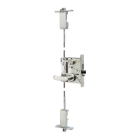
Finishing Caps
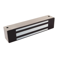
Maglock
Diagram 13 Secure Maglock
body and add finishing caps
Diagram 14 Maglock and Strike Plate Alignment
X
Y
0
0
(–)
(–)
(+)
(–) (+)
(+)
(–)
(+)
Magnalock
Strike Plate
Install the Magnalock
1 PULL the lock wire into frame and to desired location.
2 APPLY thread lock to mounting screws.
3 MOUNT lock body to frame using
supplied hardware (see Diagram 13).
4 INSERT the tamper finish caps into the
mounting screw holes (see Diagram 13).
5 ENSURE the Magnalock and strike plate are
in proper alignment (see Diagram 14).
NOTE: When installing the Magnalock and strike plate,
each should be in proper alignment to the other
(see Diagram 14). This is considered critical for the
operation of both the BondSTAT and DPS. However, there
are alignment tolerances, see table in Diagram 14, for each
model of Magnalock, but these should be viewed as the
extreme— the installation desire is always total alignment.
CAUTION The Magnalock and strike plate must
be in proper alignment or the BondSTAT and
DPS functions will not operate correctly
 Loading...