6 of 8
SERIES “B” BONDSTAT
Magnalock
RED
WHITE
GREEN
ORANGE
BLACK
DC
Power Supply
Access
Control Device
120
VAC Input
12/24
VDC
Output
NC
C
NO
REF.
LOCK
STATUS
+
–
NO
C
NC
RED
YELLOW
BLUE
BROWN
BLACK
DC
Power Supply
Access
Control Device
SERIES “D” DPS
Magnalock
120
VAC Input
12/24
VDC
Output
NC
C
NO
REF.
LOCK
STATUS
+
–
NO
C
NC
RED
WHITE
GREEN
ORANGE
YELLOW
BLUE
BROWN
BLACK
DC
Power Supply
Access
Control Device
SERIES “BD” DPS
Magnalock
120
VAC Input
12/24
VDC
Output
NC
C
NO
REF.
LOCK
STATUS
REF.
DOOR
STATUS
+
–
NO
C
C
NC
NO
NC
Wiring
WARNING: A shock hazard may occur if the
Magnalock is operated from a DC power supply that
is connected to earth ground or not isolated.
CAUTION: The Magnalock must be operated from
DC power supply of appropriate capacity and voltage.
The DC output of the power supply must not be
connected to earth ground but must be isolated,
or possible damage to the product could result.
Reference Diagrams 15-18 for wiring by model.
NOTE: In order to confirm that the DC outputs of a power
supply are isolated, it can be checked with an ohmmeter
between earth ground and +V, and then between earth
and 0V (negative). There should not be continuity.
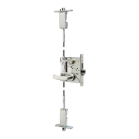
Diagram 15 Typical Magnalock Connections
Diagram 16 Connections for BondSTAT “B” Version (5 wires)
Diagram 17 Connections for DPS “D” Version (5 wires)
Diagram 18 Connections for “BD” Version (8 wires)
DC
Power Supply
Access
Control Device
RED
BLACK
Standard Version
2-wire Magnalock
120
VAC Input
12/24
VDC
Output
NC
C
NO
+
–
BondSTAT “B” Version
• GREEN and WHITE wires supply electrical
connection when the lock is ON and SECURE.
• ORANGE and WHITE wires supply electrical
connection when the lock OFF or UNSECURE.
DPS “D” Version
• BLUE and YELLOW wires supply electrical
connection when the door condition is CLOSED.
• BROWN and YELLOW wires supply electrical
connection when the door condition is OPEN.
 Loading...