04/30/21
Copyright © 2016, 2019, 2021, Sargent Manufacturing Company, an ASSA ABLOY Group company. All rights reserved.
Reproductions in whole or in part without express written permission of Sargent Manufacturing Company is prohibited.
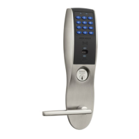
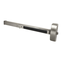
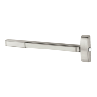
IN120 / IN220 Exit Device
1-800-810-WIRE • www.sargentlock.com • A8185D
7
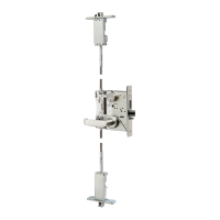
Parts Breakdown (Continued)
6
ITEM PART No. DESCRIPTION REQ’D
1 -- Cylinder Assembly (Reference Catalog for Available Cylinders) 1
2 -- Lever (Reference Catalog for Available Styles) 1
3 97-4105 Exit Trim (ET) With Cylinder 1
97-4106 Exit Trim (ET) Without Cylinder
52-4845 Motor Assembly (Separate - not shown) 1
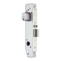
4 68-7255 Chassis Assembly 1
68-7256 Chassis Assembly (Fire Rated)
68-5836 Chassis Assembly (Latch Guarding)
68-5837 Chassis Assembly (Fire Rated Latch Guarding)
5 01-4451 1/4-20 x 2-3/8” ET Screws 2
6 01-2273 #10 x 1-1/4” Chassis Screws 4
01-1185 #10-24 x 3/4” Chassis Screws 4
7 97-0052 #8-32 x 5/16” Cover Screws 4
8 68-0406 Chassis Cover 1
68-1014 Chassis Cover (With Guarding)
8877/8878 x ET x Lever Design IN220 Rim Exit Device
4
1
2
3
7
8
5
6
 Loading...