1-800-810-WIRE • www.sargentlock.com • A8205B 20
Copyright © 2018, Sargent Manufacturing Company, an ASSA ABLOY Group company. All rights reserved.
Reproductions in whole or in part without express written permission of Sargent Manufacturing Company is prohibited.
01/31/18
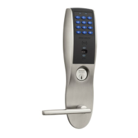
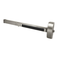
IN220 Exit Device
1. Tuck excess cable into wire hole on inside of door.
2. Secure the mounting assembly while ensuring proper
alignment of outside reader and fully tighten the (2) through-
bolts on the inside of the door to secure the reader and plate
to the door.
Secure the following connectors to their respective terminals (Fig. 10A, B):
A. Secure the 4-pin DPS connector.
B. Secure the 10-pin lock body assembly connector.
CAUTION - Do not touch or allow debris to enter connector contacts.
Secure Mounting Plate
IMPORTANT: Do not run wires through bottom hole in plate (Fig. 10A, B)
- it will damage wires and the controller connector. Route wires around
flange, do not route wires through the flange hole (Fig. 10B).
C. Secure the 24-pin card reader connector (Fig. 10B).
10 Installation of Connectors
D. Crimp* RJ45 to Cat 5e cable from hinge (Fig. 10C).
*For more detail, refer to section (5) ‘Installation Wiring’,
“A - Frame Harness Installation”.
Ground
Lugs
DPS (4-pin)
A
Lock
Body
(10-pin)
Fig. 10A
B
Reader
(24-pin)
Board-to-Board
Connector
Fig. 10B
TIA/EIA 568-B Standard Wiring
1
2
3
4
5
6
7
8
Do not confuse pair numbers with pin numbers. A pair number is
used for reference only (eg: 10BaseT Ethernet uses pairs 2 & 3). The
pin numbers indicate actual physical locations on the plug and jack.
PIN Wire Pair
Number
1 White/Orange 2
2 Orange 2
3 White/Green 3
4 Blue 1
5 White/Blue 1
6 Green 3
7 White/Brown 4
8 Brown 4
Crimp* to RJ45-M
Connector
Cat 5e cable
from hinge
RJ45-M
C
Fig. 10C
1
8
pin
8
1
pin
D
 Loading...