Copyright © 2019-2020, ASSA ABLOY Accessories and Door Controls Group, Inc. All rights reserved. Reproduction in whole
or in part without the express written permission of ASSA ABLOY Accessories and Door Controls Group, Inc. is prohibited.
80-9360-1035-020 Rev 3 03/20
6
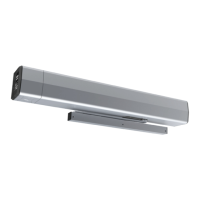
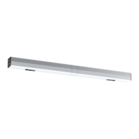
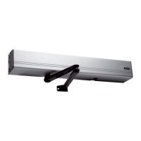
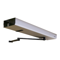
D6001DE-R Double Unit Series (Double Egress) Power Operator
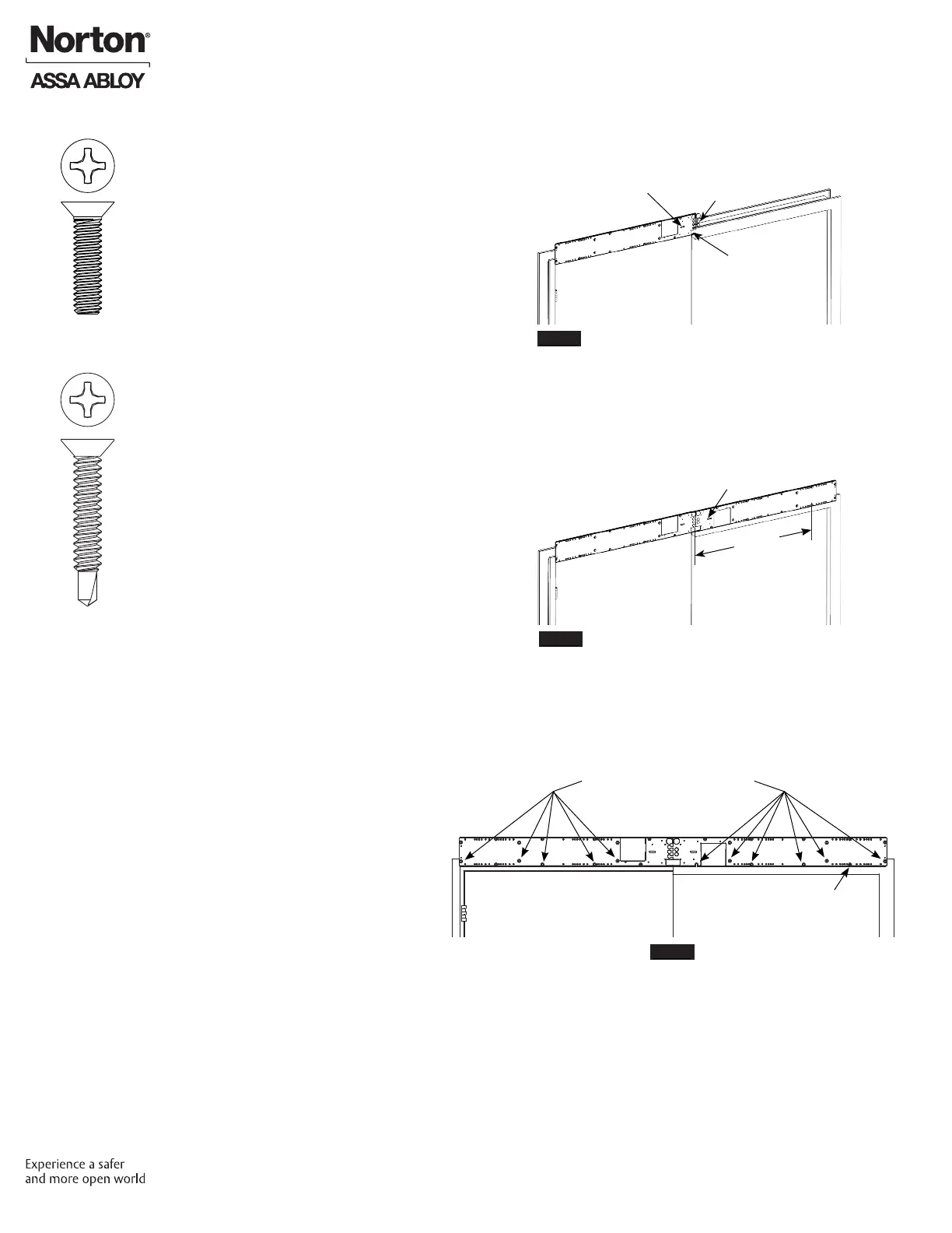
B. Mount Backplates.
1. Select backplate with 2 small “ngers” for
interlocking plates and marked “Mount This Plate
First” from Box 1. (This is LEFT backplate.)
2. Slide left backplate over mounting screws. (Figure 4)
NOTE: Left backplate conduit slot is ALWAYS at
bottom of plate and toward center of opening.
3. Use level in backplate to align then tighten
mounting screws. (Figure 4)
4. Interlock right backplate (3 small “ngers”) from Box
2 with left backplate. (Figure 5)
NOTE: Right backplate conduit slot is ALWAYS at
bottom of plate and center of opening.
5. Use level on right backplate to ensure proper
alignment. (Figure 5)
6. Using backplate as template, mark conduit slot and
Dim D mounting hole. (Figure 5)
For pair of 36" doors:
Dim D = 30-9/16"
For pair of 42" doors:
Dim D = 36-9/16"
For pair of 48" doors:
Dim D = 42-9/16"
NOTE: Dim D should be 1" up from Push side frame
rabbet if backplate is properly aligned.
7. Drill hole for mounting screw at Dim D.
8. Using supplied backplate screw pack in Box 2, insert
screw into prepared mounting hole.
(Figure 6)
For Metal Frame: Use one (1)
1/4-20 x 1" at head machine screw.
For Wood Frame: Use one (1)
#14 x 1-1/2" at head self-drilling screw.
NOTE: Do not tighten mounting screw at this time.
Leave 5/16" minimum (thickness of backplate)
between frame face and back of screw head.
9. Using countersunk holes in backplates as a template,
drill/tap remaining eleven (11) mounting holes: 1/4-
20 for steel frame or #14 for wood frame. (Figure 6)
Remaining Mounting Holes
Conduit Slot
Built-in Level
Prepare Frame and Doors
Figure 4
Figure 5
Figure 6
Two Fingers
Built-in Level
Dim D
OR
First Mounting
Screw
 Loading...