21
200V operation:
q Snuggly twist the BLACK and BROWN wires together.
q Snuggly twist the WHITE and BRN/ORG wires together.
q P re p a re and trim the BLK/WHT wire to 9” (230mm).
q Locate the AC SW PCB, and on it you will see the label “OUT” and
two solder pads.
q I n s e rt the BLK/WHT wire into either one of these pads from the top
and solder from the re a r, trim any excess lead.
q Trim the ORANGE wire to 9” (230mm). Strip 3/8” (9.5mm) and lightly
tin this wire .
q Slide a piece of heatshrink tubing onto this wire .
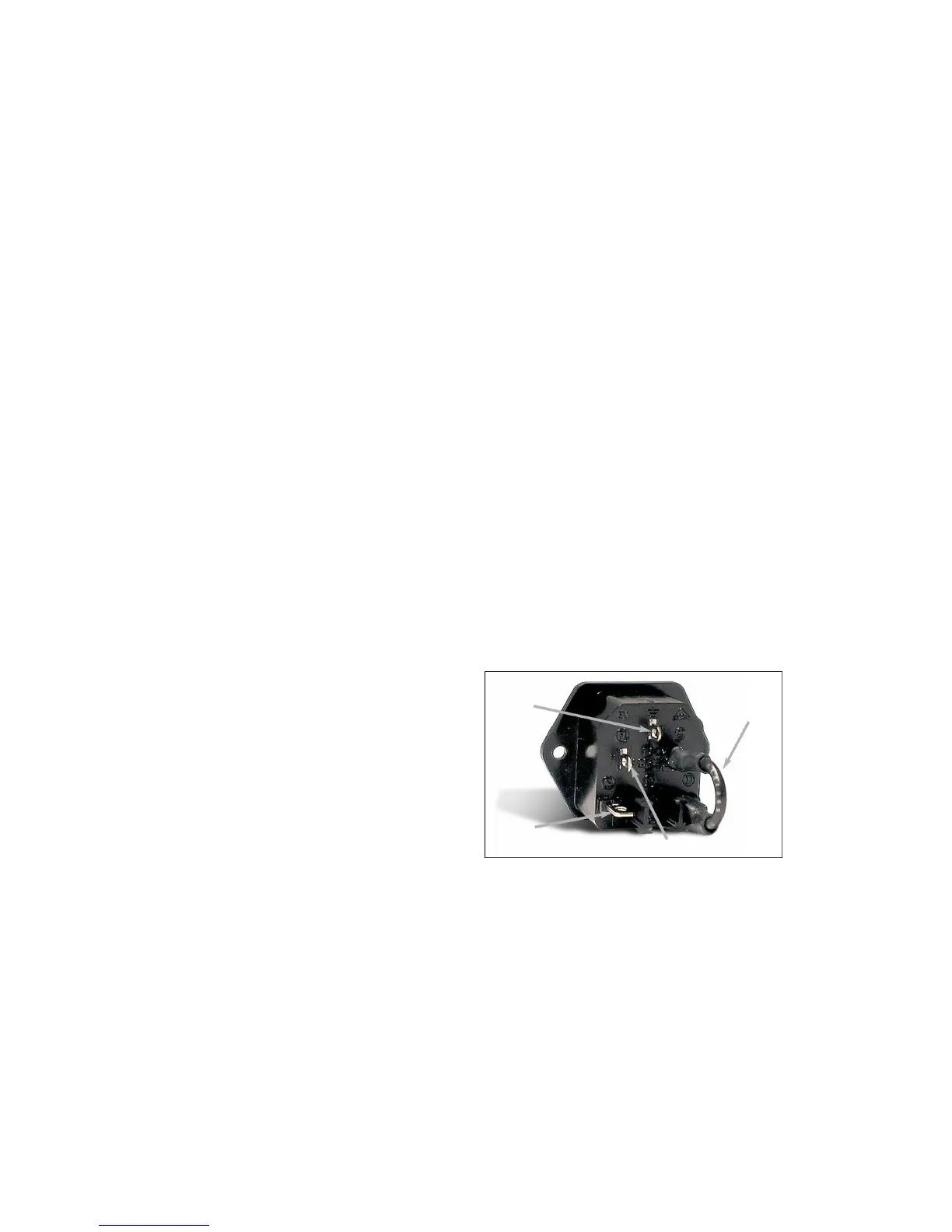
q This ORANGE wire is then soldered to the IEC AC module, to the pin
labeled ‘N’ (middle terminal). I know that you will not be able to see
this very will so observe the photo.
q Once soldered on, slide the heatshrink tubing over this connection
and shrink it into place.
q The last remaining WHITE & BRN/ORG pair connects to each other.
Trim these wires to 9” (230mm). Strip 3/8” (9.5mm) and lightly tin these
w i re s .
q We will make an inline ‘pigtail’ wire termination. Holding the wire s
side by side, twist the two leads together and solder.
q Slide a 1” (25mm) piece of Heatshrink tubing over this connection
half way. Shrink this and fold over the loose end onto itself and apply
a 1/2” (13mm) piece of heatshrink tubing over the first one and shrink
it again.
q T h ree down and one to go. The last remaining BLACK & BROWN
pair do not connect to anything, not even each other. The truth of it is
though, these wires will be live and must be treated with care to
p revent an electro c u t i o n .
q On the BLACK & BROWN wires are trimmed to 9” (230mm), more
than cutting off any of the exposed wire lead ends.
q Slide a piece of 1” (25mm) long small heatshrink tubing (1/8”), onto
each wire end, but only half way. Shrink the tubing in place and fold
the loose end back against the wire. Take another piece of 1” (25mm)
long 3/16” tubing and slide it over BOTH of these wires to couple the
ends together.
q You have rolled the dice, please advance down to ‘STICKY Pad
P l a c e m e n t ’ .
220V operation:
q Snuggly twist the BLK/WHT and BROWN wires together.
q Snuggly twist the WHITE and BRN/ORG wires together.
q P re p a re and trim the BLACK wire to 9” (230mm).
q Locate the AC SW PCB, and on it you will see the label “OUT” and
two solder pads.
q I n s e rt the BLACK wire into either one of these pads from the top and
solder from the re a r, trim any excess lead.
q Trim the ORANGE wire to 9” (230mm). Strip 3/8” (9.5mm) and lightly
tin this wire .
q Slide a piece of heatshrink tubing onto this wire .
q This ORANGE wire is then soldered to the IEC AC module, to the pin
labeled ‘N’ (middle terminal). I know that you will not be able to see
this very will so observe the photo.
q Once soldered on, slide the heatshrink tubing over this
connection and shrink it into place.
q The WHITE & BRN/ORG pair connects to each other. Trim these
w i res to 9” (230mm). Strip 3/8” (9.5mm) and lightly tin these wire s .
q We will make an inline ‘pigtail’ wire termination. Holding the
w i res side by side, twist the two leads together and solder.
q Slide a 1” (25mm) piece of Heatshrink tubing over this
connection half way. Shrink this and fold over the loose end onto
itself and apply a 1/2” (13mm) piece of heatshrink tubing over the
first one and shrink it again.
q T h ree down and one to go. The last remaining BLACK & BROWN
pair do not connect to anything, not even each other. The truth of it is
though, these wires will be live and must be treated with care to
p revent an electro c u t i o n .
q On the BLACK & BROWN wires are trimmed to 9” (230mm), more
than cutting off any of the exposed wire lead ends.
q Slide a piece of 1” (25mm) long small heatshrink tubing (1/8”), onto
each wire end, but only half way. Shrink the tubing in place and fold
the loose end back against the wire. Take another piece of 1” (25mm)
long 3/16” tubing and slide it over BOTH of these wires to couple the
ends together.
q You have rolled the dice, please advance down to ‘STICKY Pad
P l a c e m e n t ’ .
240V operation:
q Snuggly twist the WHITE and BROWN wires together.
q Snuggly twist the BLK/WHT and BRN/ORG wires together.
q P re p a re and trim the BLACK wire to 9” (230mm).
q Locate the AC SW PCB, and on it you will see the label “OUT” and
two solder pads.
q I n s e rt the BLACK wire into either one of these pads from the top and
solder from the re a r, trim any excess lead.
q Trim the ORANGE wire to 9” (230mm). Strip 3/8” (9.5mm) and lightly
tin this wire .
q Slide a piece of heatshrink tubing onto this wire .
q This ORANGE wire is then soldered to the IEC AC module, to the pin
labeled ‘N’ (middle terminal). I know that you will not be able to see
this very will so observe the photo.
q Once soldered on, slide the heatshrink tubing over this connection
and shrink it into place.
q The WHITE & BROWN pair connects to each other. Trim these wire s
to 9” (230mm). Strip 3/8” (9.5mm) and lightly tin these wire s .
q We will make an inline ‘pigtail’ wire termination. Holding the wire s
side by side, twist the two leads together and solder.
q Slide a 1” (25mm) piece of Heatshrink tubing over this connection
half way. Shrink this and fold over the loose end onto itself and apply
a 1/2” (13mm) piece of heatshrink tubing over the first one and shrink
it again.
q T h ree down and one to go. The last remaining BLK/WHT &
BRN/ORG pair do not connect to anything, not even to each other. The
t ruth of it is though, these wires will be live and must be treated with
c a re to prevent an electro c u t i o n .
q On the BLK/WHT & BRN/ORG wires are trimmed to 9” (230mm),
m o re than cutting off any of the exposed wire lead ends.
q Slide a piece of heatshrink tubing onto each wire end, but only half
w a y. Shrink the tubing in place and fold the loose end back against
the wire. Take a third piece of tubing and slide it over BOTH of these
w i res to couple the ends together.
You have rolled the dice, please advance down to ‘STICKY Pad
P l a c e m e n t ’ .
AC SW PCB Mounting:
S o rry for the switching around of instructions but we need to mount
this AC Switch PC board before going any furt h e r.
q #6-32 1/4” Philips screws x 2
q #6 lock washers x 2
q The lonely Black wire from the IEC ‘L’ terminal (top one), is to be
connected to the solder pad labeled “BLK”. Solder this wire from the
back side of the AC SW board, and trim any excess wire .
q F i rmly secure this PCB now to the side panel using the #6 scre w s
and #6 lock washers. CUE: Secure the top screw first. This will hold
the PCB in place while struggling to get the lower one installed.
q Good work, more on to ‘Welcome travelers...’.
Live
wire A
B l a ck
N e u t r a l
Link
wire C
B l a c k
G ro u n d
wire B
G r e e n
 Loading...