78
B e f o re you start assembling your SET-300B, please take a few
minutes to read this preface on the construction manual and the kit.
Zen and the Art of Electronics Assembly:
Assembling a high quality electronic device re q u i res a certain frame
of mind. The object is not to rush through and get the kit assembled
as quickly as possible, but to methodically and correctly put together
the pieces of this audio jigsaw puzzle. The kit could take as long as 6-
8 hours to complete, so plan your attack accordingly and take bre a k s
often, you will find the natural places to do so as you go through the
assembly steps. The final kit appearance will benefit from your re s t e d
m i n d .
If the instructions are followed to the letter, the amplifier will work
c o rrectly right from the start. If you try to assemble the kit purely fro m
the pictures/illustrations without reading the body of the text, your unit
will most likely not work.
Please note that this kit is not intended for the complete novice. A
c e rtain level of competency is assumed in electronics assembly - i.e.
the ability to solder, and to be able to use a voltmeter/multimeter.
General Instructions:
W h e re necessary a simple overview of the upcoming step is
p resented to you before you actually do that pro c e d u re. This little
p reamble will help to clarify the next assembly step and give you a
b roader understanding of the construction methods to use, and
hopefully aid you in getting it right the first time. Following this is a list
of the parts or components that will be needed or constructed in this
immediate section, then a detailed description of the assembly
p ro c e d u r es for that section.
The top of the printed circuit boards is the one side that has the white
s i l k - s c r eening on it. There f o re you know that the backside has no
s c reening on it and no parts, except it is the backside that the tube
sockets will be mounted to.
Parts Count:
While every precaution has been taken to ensure that you have
received a complete kit, your kit has been picked and packed by
humans. There f o re, please use the Parts List on page 4, to ensure
that you have all parts present and accounted for. Before you
convince yourself that something is missing, check again! Larg e
c a rd b o a r d boxes are notorious for hiding small parts, as are the
packing materials.
Stuffing the PC Boards:
If you inspect the main board (this is the largest of the boards with
which your are supplied with), you will notice that all parts locations
have been labeled with the appropriate part re f e r ence designator.
Each diff e rent set of components has been placed in its own
individual bag, which has its own label which lists the part type. (Yo u
will find the re f e rence designators listed on the Parts List.) There f o re ,
when you are asked to install the resistor R1, you simply pro c u re the
labeled bag with that part in it. Once the part is installed and soldere d
in place, you can check that component off the supplied checklist in
this manual. There are also several photos and diagrams detailing
p a rts placement to reduce any possible confusion that may arise
re g a rding parts placement. Please note too, that there may be some
subtle diff e rences between some of the parts shown in the
photographs and those supplied with your kit. On occasion, our
technical staff may substitute parts with ones of equal or higher
q u a l i t y.
N O T E : Talking about part substitutions, there are Signature part s
upgrade kits available for the SET-300B. These upgrade kits re p l a c e
components in the signal path, input wiring, power supply filter caps,
coupling caps, the addition of film bypass caps, and
vibration/isolation components. (see page 25 for details)
The parts for your Assemblage kit have been packaged into several
g roups: capacitors, resistors, semi-conductors, and hard w a re. Each
component type is individually packaged to allow for ease of
identification.
The process of stuffing the main board with parts is in fact a re l a t i v e l y
simple pro c e d u re - Generally the sequence will be to simply obtain
the bag containing the appropriate part, carefully bend the leads,
place the part into the holes in the PC board, then solder and trim the
leads. (Please review our soldering instructions on the next page).
Soldering:
Let it be said once, to get it out of the way - all soldering must be done
with rosin core solder! There is no warranty on equipment in which
acid core solder has been used. Please use the silver solder
p rovided in the kit.
Wire Stripping:
Unless otherwise instructed elsewhere in this manual, the norm a l
p ro c e d u re to ‘pre p a re’ a cut wire is as follows;
q Trim or cut the wire to the desired length.
q Strip back the wire jacket 3/16”(~5mm), to expose the wire inside.
Use your favorite tool, the knife or wire strippers. If you are using the
knife, please be careful and read the instructions on the following
p a g e .
q Twist the wire strands to gather them together and then solder them.
This is called the ‘tinning pro c e s s ’ .
Mechanical Assembly:
The SET-300B has been designed with ease of assembly in mind. To
this extent, the chassis has been designed with built-in standoffs, to
which the PC boards are attached. This allows the PC boards to be
easily installed and re m o v e d .
T h e re is a minimum of wiring involved in putting this kit together -
generally the power transformer must be wired to the PC boards, the
output transformers connect to the speaker binding posts and the
300B sockets dire c t l y, and the IEC socket connects the power
t r a n s f o rmer and AC switch board. The Mute switch and the input (I/P),
RCA jacks are wired to the Main PC board .
We will leave most wiring until the last few steps, as we will first
c o n c e rn ourselves with correctly placing and soldering all the
components to the PC board s .
Please be sure to follow the installation instructions closely, because
some important mounting details etc. may be included in any step.
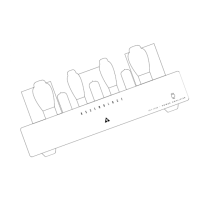
Before You Start - Kit Overview
 Loading...