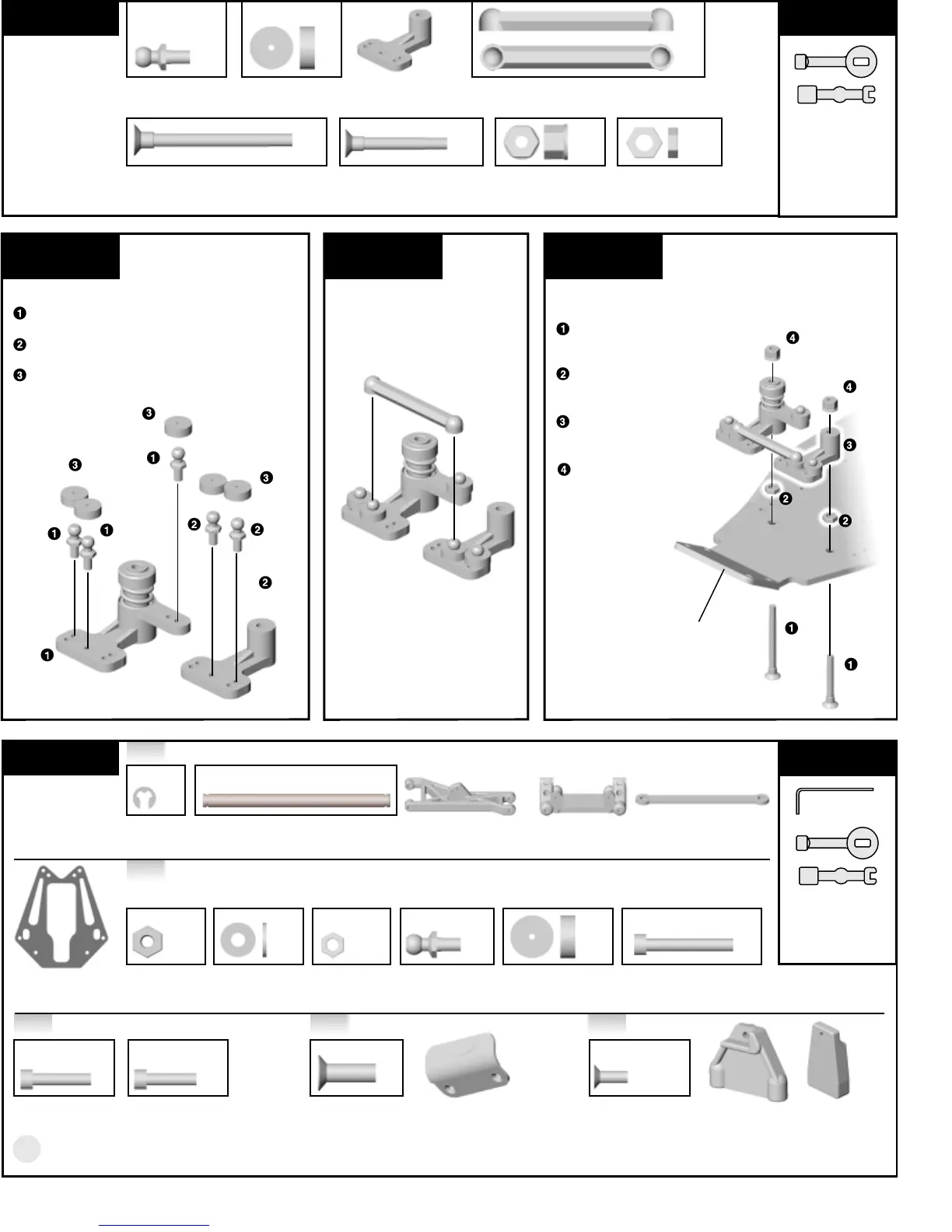
s t e p 4
SERVO SAVER
INSTALLATION
Install the two #7306 long
and short servo saver
screws into the chassis.
Install the two #8182 plain
nuts onto the servo saver
screws.
Place the servo saver
assembly over the two
screws.
Thread on two #6222
nylon locknuts. Tighten the
nuts down just enough to
remove any
play up and
down in the
assembly, but
DO NOT OVER-
TIGHTEN.
7215, 7216*, qty 1
front shock tower
Step 3 Step 5Step 4
4
B A G A
REMOVE THESE
PARTS FOR:
Steps 2-4
T O O L S U S E D
s t e p 2
SERVO SAVER ASSEMBLY
Install the three #6270 short ball ends
into the servo saver arms as shown.
Install the two #6270 short ball ends into
the #7531 bellcrank as shown.
Add the #6272 foam dust covers to the
ball ends.
6270, qty 5
short ball end
1:1
6270
6270
6270
6270
7531
bellcrank
6270
6272
6272
6272
s t e p 3
SERVO SAVER ASSEMBLY
Snap the #6265 drag link onto
the two inner ball ends.
1:1
6272, qty 5
ball end dust cover
1:1
1:1 1:1 1:1 1:1
7306, qty 1
long servo saver screw
6265, qty 1
drag link
7306, qty 1
short servo saver screw
6222, qty 2
nylon locknut
8182, qty 2
plain nut
7531, qty 1
servo saver bellcrank
B A G B
REMOVE THESE
PARTS FOR:
Steps 1-6
T O O L S U S E D
6299, qty4
e-clip
1:1
1/16", 3/32"
7209, qty 2
front inner hinge pin
1:1
7206, qty 2
left and right front a-arms
7207, qty 1
front bulkhead
7208, qty 1
aluminum bulkhead
support
1:1 1:1 1:1 1:1 1:1 1:1
6295, qty 2
plain nut
6936, qty 2
#4 flat washer
7260, qty 2
plain nut
6270, qty 2
short ball end
6272, qty 2
ball end dust cover
6927, qty 2
4-40 x 3/4 SHCScrew
Step 1
Step 2
1:1
6925, qty 2
4-40 x 1/2 SHCScrew
1:1
6280, 6942*, qty 4
8-32 x 1/2 FHScrew
1:1
7673, qty 4
4-40 x 5/16 FHScrew
TEAM/FT
7314, qty 2
nose tube mount
(left and right)
8182
8182
8182
8182
servo saver
assembly
1:1
7838*, qty 2
4-40 x 7/16 SHCScrew
RTR
7767, qty 2
nose tube mount
TEAM/FT
7774, qty 1
front bumper
7306
long
7306
short
6222
6222
TEAM/FT 7769
RTR 7765