Do you have a question about the Associated Research Omnia 8106 and is the answer not in the manual?
Describes the instrument's graphic LCD, soft keys, numeric data entry, and arrow/enter keys.
Details the high voltage indicator and scanner status LEDs.
Covers the power switch, reset button, and test button for instrument operation.
Lists connectors for high voltage output, current output, and Kelvin voltage sensing.
Details terminals for high voltage output, current output, and voltage sensing.
Covers scanner interface, bus interface, and remote signal connections.
Includes calibration button, fuse receptacle, chassis ground, and cooling fans.
Describes input power, output terminals (L, N, GND, RTN), and scanner outputs.
Details the compartment for an external measuring device PCB.
Guides on setting voltage, connecting power, and turning on the instrument.
Explains how to add new tests and change test parameters.
Details the process for saving and recalling test programs.
Illustrates test connections using an adapter box for the 8104 model.
Shows adapter box connections for the 8105 and 8106 models.
Describes test lead connection for Class II products and initiating a test.
Explains how to view, review, and understand test results on the screen.
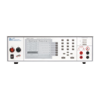
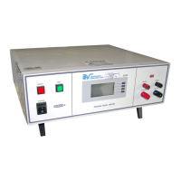
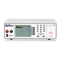
The OMNIA is a series of electrical safety testers, specifically models 8104, 8105, and 8106, designed for performing various electrical safety tests such as Hipot (AC Withstand, DC Withstand), Insulation Resistance, Continuity, Run Test, and Line Leakage Test. These instruments are equipped with a range of features for setting up, performing, and reviewing test results, catering to operators familiar with Hipot and electrical safety testing.
The OMNIA instruments are primarily used for ensuring the electrical safety of devices under test (DUTs). They generate controlled voltages and currents to perform tests that verify insulation integrity, grounding effectiveness, and leakage current levels. The 8104 model is suited for ACW, DCW, IR, and Continuity tests, while the 8105 and 8106 models additionally support Run Test and Line Leakage Test. The internal scanner on the front panel allows for testing multiple high voltage and high current channels. The instruments feature a user-friendly interface for parameter entry, test execution, and result review.
| Brand | Associated Research |
|---|---|
| Model | Omnia 8106 |
| Category | Test Equipment |
| Language | English |