123
123
123
EliteConnect
720
720
ClmV
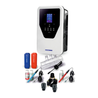
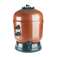
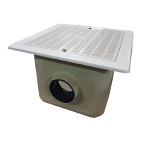
Components and installation
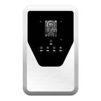
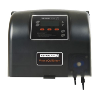
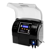
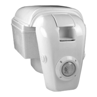
Control unit
Optional accessories
CAUTION: Always install upright on a
rigid surface in a dry, ventilated area.
We recommend installing the equipment
where it will be protected from the weath-
er. Avoid creating corrosive atmospheres.
For further information on installation and wiring, see complete
manual.
Peristaltic pump
EN
!
who have carefully read all the installation and maintenance instructions.
Elite
Connect
Mount: 8 x 50 mm
Screw: 5 x 50 mm
Connection
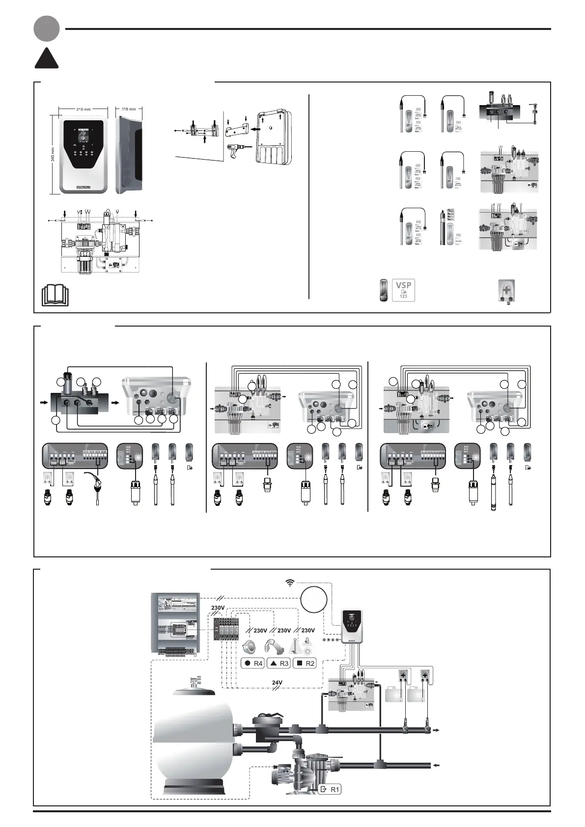
General installation diagram
Fluidra Pool
Electrical control panel
Dosing
pump
Outlet
Inlet
ORP
pH
ClpH
BLUE
VSP driver
Control Connect
pH/ORP
Control Connect
pH/PPM_panel
230 V
always on
1) pH sensor
2) ORP sensor
2
7
5
4
3
7
1
4
9) Cl injection
10) 230 Vac feed
GREEN
5) 230 V
6) Temperature
3) PPM sensor
4) VSP
7) Flow switch/inductive sensor
8) pH injection
7
7
6
2 14
10
6
6
7
1010
4
1
4
BLUE
PPM
VSP
pH
TEMP (ºC)
INDUCTIVE
SENSOR
ORP
VSP
pH
TEMP (ºC)
INDUCTIVE
SENSOR
ORP
VSP
pHTEMP (ºC)FLOW SWITCH
RED
BLUE
RED
BLUE
8 9
N.B.: This diagram is a general
representation of an installation that
includes all available options, so it
model.
Control
unit
Control Connect
pH/ORP_panel
Control Connect
pH/ORP
Control Connect
pH/PPM_panel
Control Connect
pH/ORP_panel