10
ENGLISH
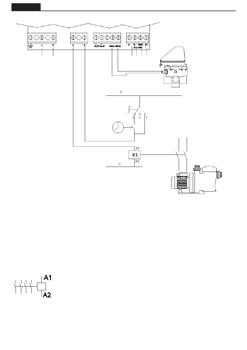
ELECTRICAL CONNECTION BETWEEN THE CONTROL CABINET AND THE VALVE
A1 / A2 are the terminals used to connect the ltration pump's contactor coil. Ter-
minal J10 of the multiport valve must always be connected to connection A1 of the
contactor coil. The J10 socket (4-5) of the selector valve must always be connected
to A1 connection of the contactor coil.
We should ensure that the contactor's operation line, which is connected in series to
the valve does not under any circumstances share the power supply with any other
device, and the intensity of the operation line never exceeds 400 mA. If this point is
omitted it may cause irreversible damage to the equipment.
In cases where another component has to be connected which needs be activated
at the same time as the pump, we recommend the use of an auxiliary contact of the
pump contactor.
In the event the supply of the valve is connected to a three-phase electrical circuit, always make the on-
nection between one phase and the neutral, never between two phases, since that way the maximum
voltage allowed by the valve electronics would be exceeded.
The control circuit (for example contactor's coil of ltration pump) is powered at U and V in this schema.
U and V can be Alternative Current (AC) where U is Line and V is Neutral, or Direct Current
(DC), where U is Vdc and V is GND.
Maximum voltage = 230 V.
ELECTRIC SUPPLY
230 Vac
TIMER
3 positions switch:
2 AUTOMATIC (TIMER)
0 STOP
1 MANUAL
Contactor's coil of Filtration
Pump
CONTACTOR
PUMP
PRESSURE SWITCH
COMMUNICATION
PROTOCOL
MODBUS