7
ENGLISH
1. VALVE CHARACTERISTICS
1.1 SPECIFICATIONS.
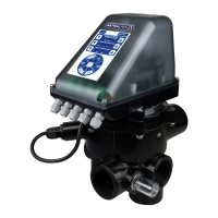
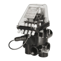
Two valve models with actuator:
- Selector valve 1 ½ " VRAC BASIC System.
- Selector valve 2 " VRAC BASIC System.
The valve assembly to the lter will be LATERAL or TOP depending on the code requested.
Materials: Valve body: ABS.
Internal distributor: PPO.
Spring: AISI-302 coated stainless steel. Screws: AISI-316 stainless steel.
Connection of the TOP, RETURN and WASTE openings through BSP or NPT female threads.
In the case of lateral mounting, the BOTTOM opening of the body is provided for bonding using glue. The
connection kit to a side lter with a 125 mm (1 ½ ") or 230 mm (2") height is included. See hydraulic
connection sheet.
Maximum working pressure: 350 kPa (3.5 bar).
Test pressure: 520 kPa (5.2 bar).
Maximum service life: 5,000 washing and rinsing programmes. Temperature range: 5 - 35 ºC.
Degree of protection of the electronic module: IP-65. Maximum power = 35 W.
Power supply: 115 - 230 VAC (50-60 Hz).
Maximum expected height use of 2,000 m above sea level.
A sensor and a resistor have been installed in the control module to maintain a suitable indoor temperature
to avoid condensation caused by thermal dierences that could damage the electronics.
Intended use: the valve is specially designed to be applied in pool ltration systems using a sand lter. The
planned number of operations is suciently dimensioned for this application. Check with the manufacturer
for other uses.
An alarm that limits the number of maximum pressure washes in a single day has been added so as to
limit its use to pool ltration systems, so that priority is given to the pool not being emptied due to poor
conguration of the system.
The hydraulic and electric operation of the valve is checked at the factory
1.2 FLOW DIAGRAM FOR THE VARIOUS VALVE OPERATING POSITIONS.
The valve should be installed in the lter following the instructions provided in the hydraulic connection
diagram.
Installation under load, the maximum water column that can be supported by the pump is six metres
(19.68 ft).
The hydraulic connections for correct operation are made by following the markings on the valve itself.
PUMP indicates the connection coming from the pump.
TOP indicates the upper input to the lter.
BOTTOM indicates the lower exit from the lter to the valve.
RETURN indicates the return from the valve to the swimming pool.
WASTE indicates the connection to the drains.