64 ASUS SP97 / SP97-V User’s Manual
Layout and Connectors
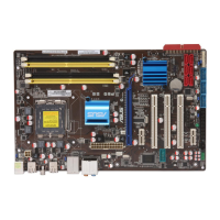
VII. ASUS I-A16C Audio Card
Microphone
Speaker Out
PC Speaker In
Sony Audio In
Wave Table Upgrade
Line Out
Line In
MIDI/Game
Mitsumi Audio In
Panasonic Audio In
Volume Control
PC Speaker Out
Connectors
The audio input connectors are used when you wish to control software mixer set-
tings (e.g., bass, treble, volume) for CDs that are played with your CD-ROM drive.
If the “Audio Out” from the CD-ROM drive is not connected to the “Audio In” on
the card, you can only use the direct output located in the front panel of the CD-
ROM drive and adjust volume level by the knob.
CD-Audio Connector Pin Definitions
Sony Audio In Mitsumi Audio In Panasonic Audio In
Pin Definition Pin Definition Pin Definition
l Right Signal 1 Ground 1 Left Signal
2 Ground 2 Left Signal 2 Ground
3 Ground 3 Ground 3 Right Signal
4 Left Signal 4 Right Signal -- ----
PC Speaker In PC Speaker Out Volume Control
Pin Definition Pin Definition Pin Definition
1 Mono Signal 1 Right Signal 1 Ground
2 Ground 2 Ground 2 Volume Up
-- ---- 3 Left Signal 3 Ground
-- ---- 4 Ground 4 Volume Down
-- ---- -- ---- 5 Ground
VII. ASUS I-A16C
(Layout / Connectors)