Signal Generator
The Channel Inputs and Matrix Output can have a signal
generator applied to them� The option can be found in the
Channel Matrix and Mix Matrix pages by right clicking the
mouse� The signal generator can be activated with the
“ON” buttons and assigned to the appropriate mixes using
the matrix/channel select section below the controls�
There are 4 different signals available, including White
Noise and Pink Noise – ideal for setup of systems – and
sine and sweep waves – for testing of equipment and for
general setup purposes�
Sine: The sine wave can be selected between 20 Hz and
20 kHz. The signal level can also be adjusted, and the
signal can be turned on and off�
Sweep: When using the sweep wave, a lowest and
highest frequency can be selected� The sweep wave will
move between these frequencies and small increments�
The hold time for each frequency can be selected by the
users� There are also controls for adjusting the signal level and turning the sweep wave on and off�
Pink Noise: The pink noise function includes level controls and on/off button�
White Noise: Like the pink noise, the white noise only offers level controls and an on/off button�
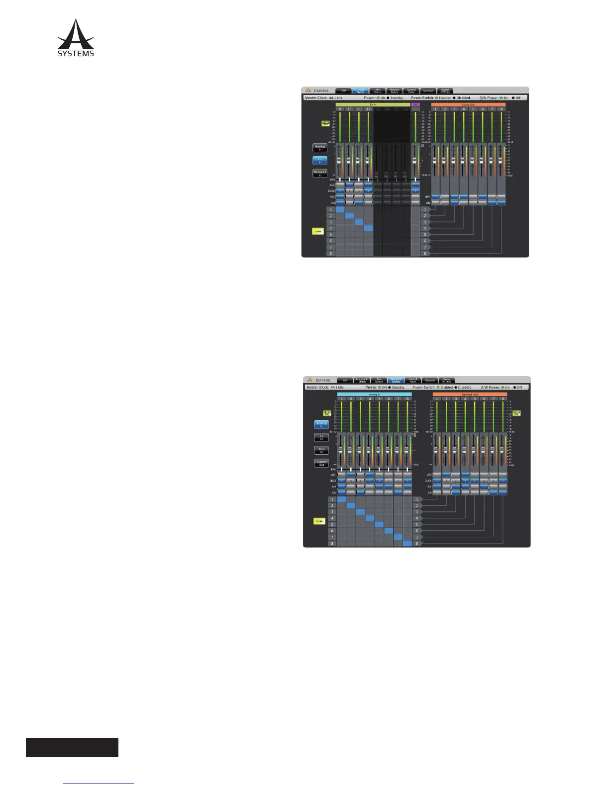
Network Matrix
Any of the incoming input signals can be assigned directly to the Network output mixes� The network matrix pages are
only used when the A Systems network expansion card is installed in the DMP808� Attenuation: Adjust the input level of
each of the individual input and output mixes�
Panning: These will let you adjust the left/right mix of the
available mixes�
ALC: This button will assign the DMP808’s Auto Level
Control to the corresponding input�
Duck: Pushing this button will apply the ducking feature to
the corresponding mix� The duck function can be activated
as ducker 1, ducker 2, or off, the settings of which are
decided by their respective menus�
INV: This button will invert the phase of the corresponding
input or matrix signal�
On: This button allows you to turn the corresponding input
signal on and off� When turned off, the signal will not be
sent to any of the matrix outputs selected�
Routing: Each of the 12 analog inputs, 8 matrix inputs
and 8 matrix outputs can be assigned to the DMP808’s 8
network outputs� These channels will appear as Network
Input connections in any networked A Systems� DMP or DMA matrix devices�
 Loading...