Installation & Servicing instructions ATAG A-Series
26
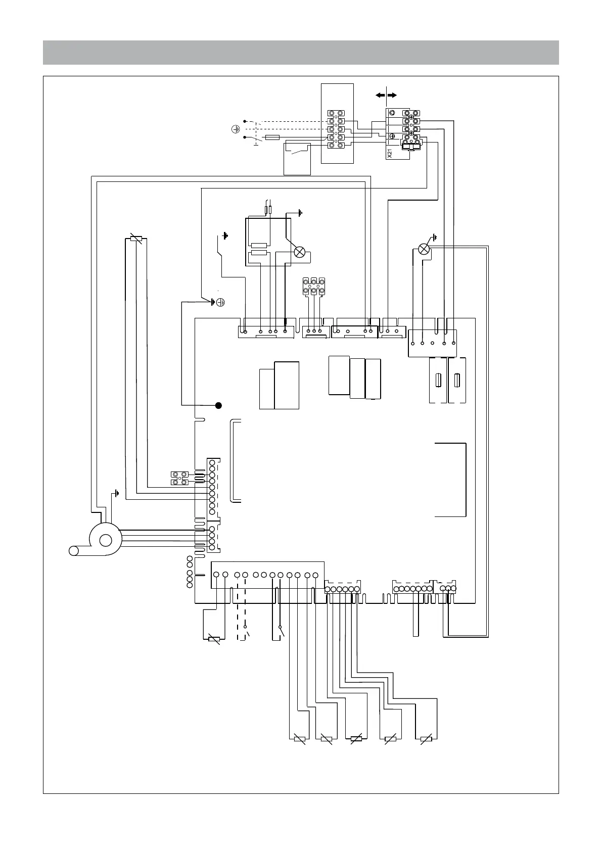
8.2 Electrical diagram Solo boilers
230V AC
SYSTEM
CONTROLS
K01
K01
K01
K1
1. EXTERNAL SAFETY CONTACT*
2.
IGNITION
3. GAS VALVE
4. IONISATION
5. EARTH
8. WATER PRESSURE
SENSOR
P1
10. FAN 230V
11 B. ALTERNATIVE: ROOMTHERMOSTAT
BATTERY POWERED*
11 A. ATAG Z ROOMTHERMOSTAT
OPTION
12. OUTSIDE SENSOR
T4
OPTION
14. FLOW SENSOR
T1
15. RETURN SENSOR
T2
16. FLUE GAS SENSOR
T5
OPTION
T 3,15 H
T 3,15 H
19.
FUSES
250V
20. SERVICE CONNECTOR
N
N
N
L
N
L
L
L
X1
X2
X4
X8
X9
X11
X12
K1
13a. EXT. DHW SENSOR
T3
OPTION
X13
X6
X7
X5
230V
FUSE
T3,15AH 250V
SL N L
1 2 3 4 5
8G.44.50.00
L N
INSTALLATION
BOILER
21.
JUNCTION
BOX
DOUBLE POLE
ISOLATOR
FUSE
13b. EXT. DHW STAT. ON/OFF
T3
OPTION
X10
brown
blue
black
18. MOTOR
3 WAY VALVE OPTION
6. PUMP
N
L
Figure 8.2.a
1. External safety contact
2. Ignition
3. Gas valve
4. Ionisation
5. Earth
6. Pump
7. Main power supply 230V
8. Water pressure sensor
10. Fan 230V
11. Room thermostat
12. Outside sensor
13a. Ext. DHW sensor (Option)
13b. Ext. DHW stat. on/off (Option)
14. Flow sensor
15. Return sensor
16. Flue gas sensor
18. External 3 way valve 230V
19. Fuses
20. Service connector
21. External switched live
connection
 Loading...