Installation & Servicing instructions ATAG A-Series
37
13.2 Maintenance activities
Only to be carried out in the event that the CO, CO
2
and/or ratio gures are in-
correct.
Required tools:
- Cross head screwdriver
- ATAG T-handle key set with 3 bits (hex key 4mm, hex key 5mm and cross head PZ2)
- Open end wrench 8mm
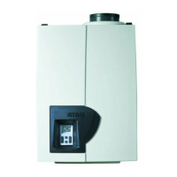
In order to perform maintenance, the following actions have to be taken:
- switch off the boiler;
- remove the screws from the 4 quick fasteners A, B, C and D (see g. 13.2.a);
- unlock the 4 quick fasteners A, B, C and D and remove the cover in a forward motion.
Air box/cover
The cover also doubles as air box:
- Clean the air box/cover with a cloth and a non-abrasive cleaner;
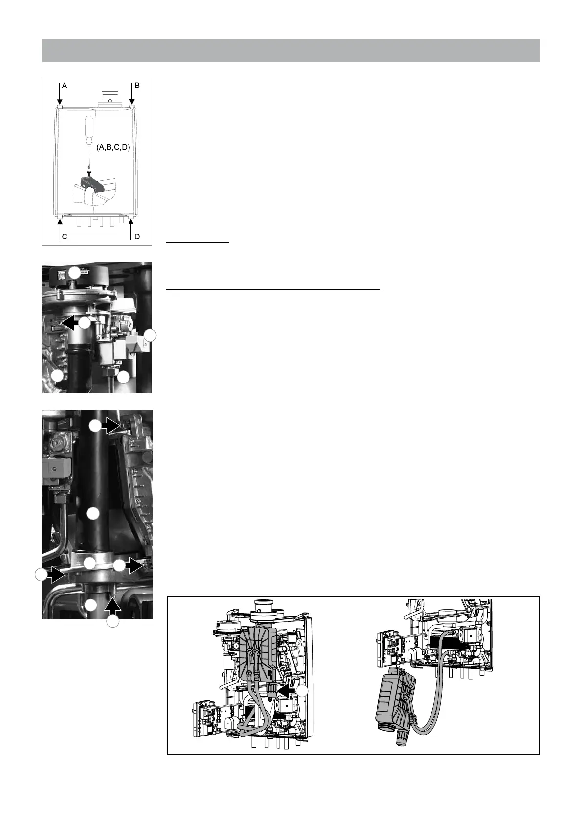
Fan unit and burner cassette (see g. 13.2.b-f)
- dismantle the igniter(1) by means of the screw of the gas block;
- pull out the plug connections (2) of the fan;
- unscrew the coupling (3) of the gas block;
- replace the gas block gasket (O-ring) with a new one, if required;
- unscrew the front crosshead screw (4) from the air supply dampener;
- A325ECX only: unscrew the siphon from the economiser (13), check for pollution,
clean it and t the siphon back on the economiser.
- unscrew (5) the siphon (6) and pull it downwards from the condensate tray;
- turn the left (7) and right (8) clamp bar of the condensate tray with the hex key a
quarter turn and pull these out in a forward motion. Note the direction of rotation (red
control cams);
- slide the ue pipe (11) or the economiser (A325ECX only) about 1 cm upwards;
- push the condensate tray (12) gently downwards and pull it out from the boiler;
- Pull the ue pipe (11) or economiser (A325ECX only) downwards out of the boiler;
- A325ECX only: hang the economiser with the metal hook on the metal bracket behind
the control unit (see g. 13.2.d)
- now turn the left (9) and right (10) clamp bars with the hex key a quarter turn and
pull these out in a forward motion. Mind the direction of rotation (red control cams);
- now remove the complete fan unit with the gas block from the heat exchanger in a
forward motion;
1
2
3
9
4
10
Figure 13.2.a
Figure 13.2.b
Figure 13.2.c
6
7
8
5
11
12
A325ECX with Economiser Figure 13.2.d
13
 Loading...