Installation & Servicing instructions ATAG A-Series
38
Figure 13.2.j
Figure 13.2.k
6
7
8
5
11
12
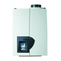
- Remove the burner cassette (18) from the ventilator unit;
- Check the burner cassette for wear and tear, pollution and any breakages. Clean
the burner cassette with a soft brush and vacuum cleaner. In the case of breakages,
always replace the complete burner cassette (18);
- Replace the gasket (17) between the burner (18) and upper casing (15), if required;
- Replace the gasket (16) between the upper casing (15) and exchanger, if required.
Heat exchanger
- Check the heat exchanger for pollution. Clean it, if necessary, with a soft brush and
a vacuum cleaner. Avoid any pollution falling down.
Top-ushing the exchanger with water is not allowed.
Reassembly takes place in reverse order.
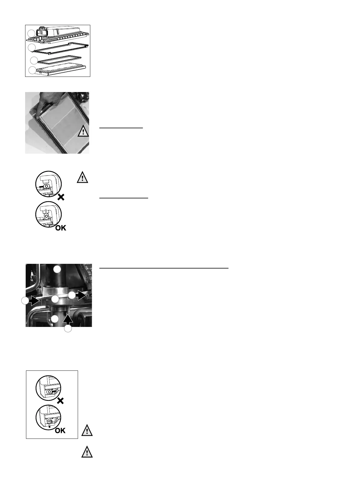
During installation pay attention to the correct position of the clamp bars. These
have to be in a vertical position.
Ignition electrode
Replacing the ignition electrode is necessary when the pins are worn.
If the inspection hole is damaged, the entire ignition electrode has to be replaced.
It is replaced as follows:
- take away the plug connections on the ignition electrode;
- push the clips on either side of the electrode outwards and take away the electrode;
- remove and replace the gasket;
Reassembly takes place in reverse order.
Siphon and condensation tray (see g. 13.2.j-l)
- rst disassemble the siphon cup (6).
Check it for pollution. If no serious pollution is found in the siphon cup, it is not
necessary to disassemble the condensation tray or clean it. If the siphon cup shows
serious pollution, the condensation reservoir should be cleaned as well.
- check the O-rings of the siphon cup and replace them if necessary.
- clean the parts by rinsing them with water.
- grease the O-rings again with acid-free O-ring grease to simplify the reassembly.
- If a leakage has occurred to the siphon, replace the entire siphon;
- remove the plug from the ue gas sensor, if any.
- turn the left (7) and right (8) lamp bar of the condensate tray with the hex key a quarter
turn and pull these out in a forward motion. Note the direction of rotation (red control
cams);
- slide the ue pipe (11) or the economiser (A325ECX only) about 1 cm upwards;
- A325ECX only: hang the economiser with the metal hook on the metal bracket behind
the control unit (see g. 13.2.d)
- now push the condensation tray (11) gently down and take it away in a forward motion;
- replace the condensation tray gasket by a new one.
- clean the polluted condensation tray with water and a hard brush.
- Check the condensation tray for leaks.
Reassembly takes place in reverse order.
Pay attention that the gasket seals completely all around during reassembly of
the condensation reservoir.
During installation pay attention to the correct position of the clamp bars. These
have to be in a vertical position.
figure 13.3.i
15
16
17
18
figure 13.2.e
Position gasket
figure 13.2.f
 Loading...