11
8 Mounting boiler frame
Install the boiler in a boiler room in accordance to the actual local regulations BS5440-2:2000.
The installation location of the boiler has to be, and remain, frost-free. The boiler casing is splash water tight
(IPX4D) and is suitable to be installed in e.g. a bathroom.
It is NOT necessary to have a purpose provided air vent in the room or internal space in which the boiler is
installed. Neither is it necessary to ventilate a cupboard or compartment in which the boiler is installed, due
to the extremely low surface temperature of the boiler casing during operation. Therefore the requirements of
BS 6798, Clause 12, and BS5440:2 may be disregarded.
The boiler can be mounted practically to any wall with the wall frame and the enclosed xing equipment. The
wall must be at and of sucient strength in order to be able to carry the boiler weight with its water content.
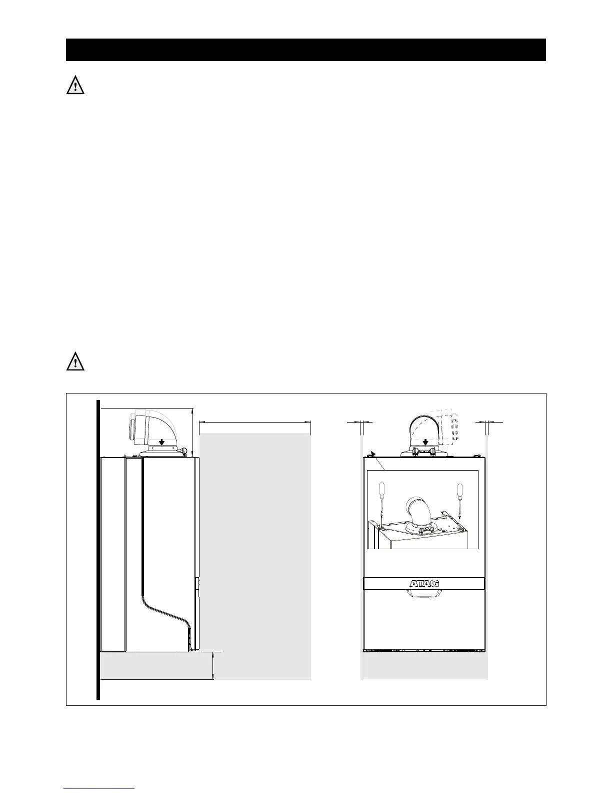
Above the boiler there must be at least 175 mm working space in order to be able to t a horizontal
concentric ue system to the rear (See chapter 9.8 for more ue options). Make sure there is sucient
service space arround the boiler according gure 8.a. The location of the boiler can be determined by using
the template.
The wall frame allows the possibity to pre-t the complete heating system before tting the boiler. Also the
ue system can be prepared. Finally tting of the ue system is done after tting the boiler. See next page for
all options for connection the heating, condensate, ue and gas installation.
Before hanging the boiler to the boiler frame remove the front panel of the boiler rst. The front panel is also
the air cabinet and is attached to the boiler case with 2 fasteners (A and B) (see gure 8.a).
Note that there is an earth cable to disconnect when removing the boiler front panel. Free space for
removing the connector is about 400 mm. Remember to connect this earth cable when placing back
the boiler front panel and take care the wire does not get stuck between front panel and boiler.
See chapter 9.8 for further procedure to t the boiler onto the boiler frame.
Service dimensions (in mm) Figure 8.a
100
2.5 2.5
400
Service space
Service space
175
Bayonet catch

 Loading...


