13
9 Connecting boiler
The boiler has the following connection pipes;
- The central heating pipes.
The boiler is provided with isolation valves on the ow and return pipe to which the installation can be
connected by means of 22mm compression ttings;
- The gas pipe.
The boiler is provided with an isolation gas valve to which the gas line can be tted with 22mm
compression tting;
- The condensation drain pipe.
It consists of a 25mm exible plastic pipe. The drain pipe can be connected to this by means of an open
connection;
- The ue gas exhaust system and air supply system.
It consists of a concentric connection 60/100 mm.
See following chapters for detailed information regarding each connection.
It is advisable to clean all of the boiler’s connecting pipes and/or to power ush the installation
before connecting it to the boiler.
9.1 Central heating system
Connect the central heating system according to the current regulations.
The boiler pipes can be connected to the installation by means of 22mm compression ttings. For connecting
to thick-walled pipe (welded or tted), adapters should be used.
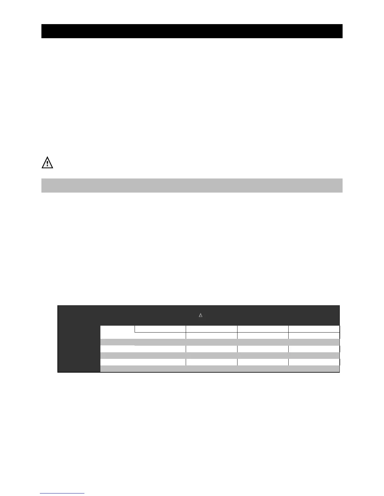
The boiler has a self-adjusting and self-protecting control system for the load. This involves checking the
temperature dierence between the ow and return water. Table 9.1.a shows the water displacement the
circulation pump can deliver for a particular installation resistance.
If the installation resistance is higher than the value stated, the control system will adjust the load until a
temperature dierence between ow and return water is reached that is acceptable for the control system.
When the temperature dierence still remains too high the boiler will switch itself o and wait until the high
temperature dierential between the ow and return water has decreased again.
The control system will, if an unacceptable temperature dierence is detected, repeatedly try to establish a
water ow. If this does not succeed, the boiler will block itself (code 154).
Pump type
Boile
Grundfos
iS 12 UPM3 15-75 7.6 460 25 250
iS 15 UPM3 15-75 9.5 570 25 250
iS 18 UPM3 15-75 11.4 680 25 250
iS 24 UPM3 15-75 15.2 910 25 250
iS 32 UPM3 15-75 20.3 1220 20 200
iS 40 UPM3 15-75 25.3 1520 20 200
Water flow rate at
T 20°C
Permissible installation resistance
Installation resistance table 9.1.a

 Loading...


