19
3-port diverter valve
Install the 3-port diverter valve on the system pipework with the valve ports is the following orientation, AB
port iS System boiler, A port hot water cylinder & B port heating system.
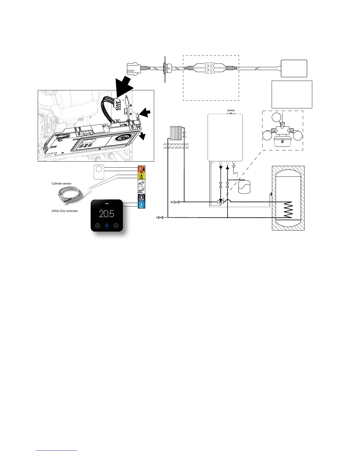
ATAG 3-port external diverter valve kit including the ONE controller (CT500111) used with an
unvented hot water cylinder.
The ATAG 3-port diverter valve is to be tted external to the boiler on the system pipework with the electrical
wiring routed back to the wiring loom diverter valve connection within the iS boiler with a connection plug and
wire included with in the 3-port diverter valve kit.
The installation will use the cylinder sensor supplied within the 3-port diverter valve kit to control the hot
water temperature. Therefore no other cylinder thermostat is required.
The ONE controller will control the heating and hot water time and temperature requirements.
The weather compensation for heating will be controlled by the boiler and ONE controller via the internet
connection and postal code weather data. An optional outside sensor (ARZ0055U) can be added to the
3-port diverter valve kit to sense the outside temperature specically for the individual property.
The installation may require altered wiring of the dual thermostat (depending on the cylinder the
manufacturer) to only use the high limit thermal cut-out of the dual thermostat.
The high limit thermal cut-out of the dual thermostat MUST be wired to interrupt the power to the 2-port valve
supplied with the unvented cylinder.
Fitting the cylinder temperature sensor
The cylinder sensor is to be tted into a sensor pocket of the unvented cylinder along with the dual
thermostat supplied with the unvented cylinder.
Wiring of components
Connect the 3-port diverter valve to the spare 3-port valve connector on the wiring loom.
Connect the cylinder sensor with the yellow connector to the yellow DHW volt free position and the ONE
control wires with the blue connector to the blue BUS volt free position on the back of the control panel.
a.
d.
c.
a.
b.
c.
B
A
AB
AB
B
AB
A B
A
a. brown
b. blue
c. black
d. grey
Junction box (not included)
3-port valve
230V
AB: iS System boiler
A: DHW Cylinder
B: Heating system
ATAG outside sensor (optional)
Cylinder sensor
ATAG One controller
1
2
3
4
5
6
7
8
9
10
11
12
Volt free
terminals
DO NOT CONNECT 230 VOLT
Figure 9.6.b

 Loading...


