36
Flue gas system
Requirements and regulations
Materials
Flue gas data
Notes
The tables below give guidance on the maximum lengths of air and flue gas tubes that may be connected. If a room sea-
led installation is being made utilising separate air and flue gas tubes, the lengths of both tubes must be added together
and not exceed the relevant value given in the tables.
The radius of any bend used in the flue gas system must not exceed 87.5°.
Walls that are sensitive to heat should be insulated.
Construct the flue system in such way that no recirculation may take place.
When the boiler is operational, it produces a white plume of condensation. This condensation plume is harmless
but may cause some inconvenience, particularly in the case of wall terminal. As a result, roof terminals are pre-
ferred. In a closed installation, roof terminals should be at the same height preventing flue gas from being
sucked in by the other boiler (recirculation). Outlets in recesses and near erected walls may also bring about
flue gas recirculation. Recirculation has to be prevented at all times.
For installation in UK please refer to installation guidance in BS6644 and IGE UP10.
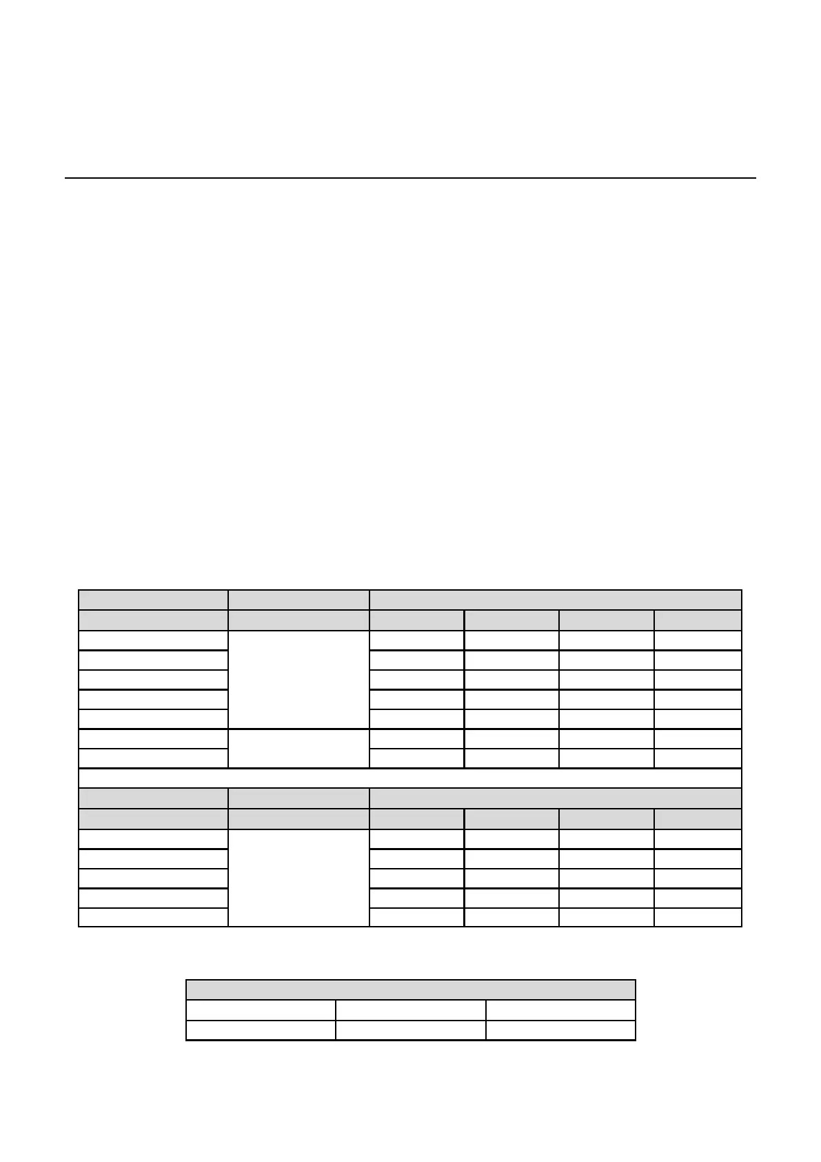
Dimensioning (reference value)
Tube size Maximum length in metres (roof terminal not included)
Changes of direction 0 2 3 4
60
Ø100 mm
82 78 76 74
70 60 56 54 52
100 34 30 28 26
120 17 13 11 9
140 16 12 10 8
170
Ø130 mm
35 30 27 25
200 30 25 22 20
Tube size Maximum length in metres (roof terminal included)
Changes of direction 0 2 3 4
60
Ø100/150 mm
14 11 9 8
70 14 11 9 8
100 12 9 7 6
120 8 5 3 2
140 9 6 5 3
Required minimum (flue enclosure) shaft cross-section
Diameter flue duct Square shafts Round shafts
100 mm 140 x 140 mm 160 mm
 Loading...


