56
Standard Schemes
ATAG XL-W + 1 Mixing circuit +1 Direct circuit + Low loss header
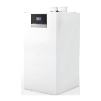
Electrical connections
A : Main power supply (230V @50Hz)
B : Clip In power (230V @50Hz)
T10: Common ow temperature sensor (10KΩ )
C : Clip-In 3 zone
RT1: Room thermostat (On/O )
RT2: Room thermostat (On/O )
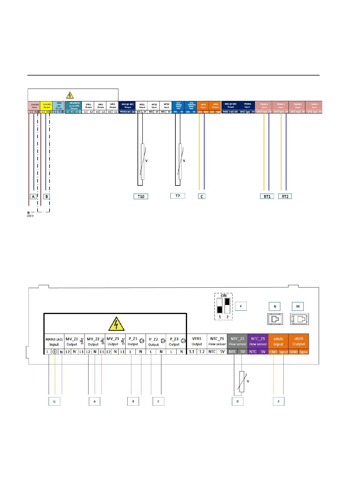
A : Mixing Valve HC2
B : Heang circuit pump HC1
C : Heang circuit pump HC2
D: Flow sensor HC2
E: Clip In connecon to boiler Ebus Input
F: DIP-switch 2 must be set in ON posion
G: Main power connecon to boiler board
BOILER MOTHERBOARD
CLIP-IN ZONE MANAGER
 Loading...


