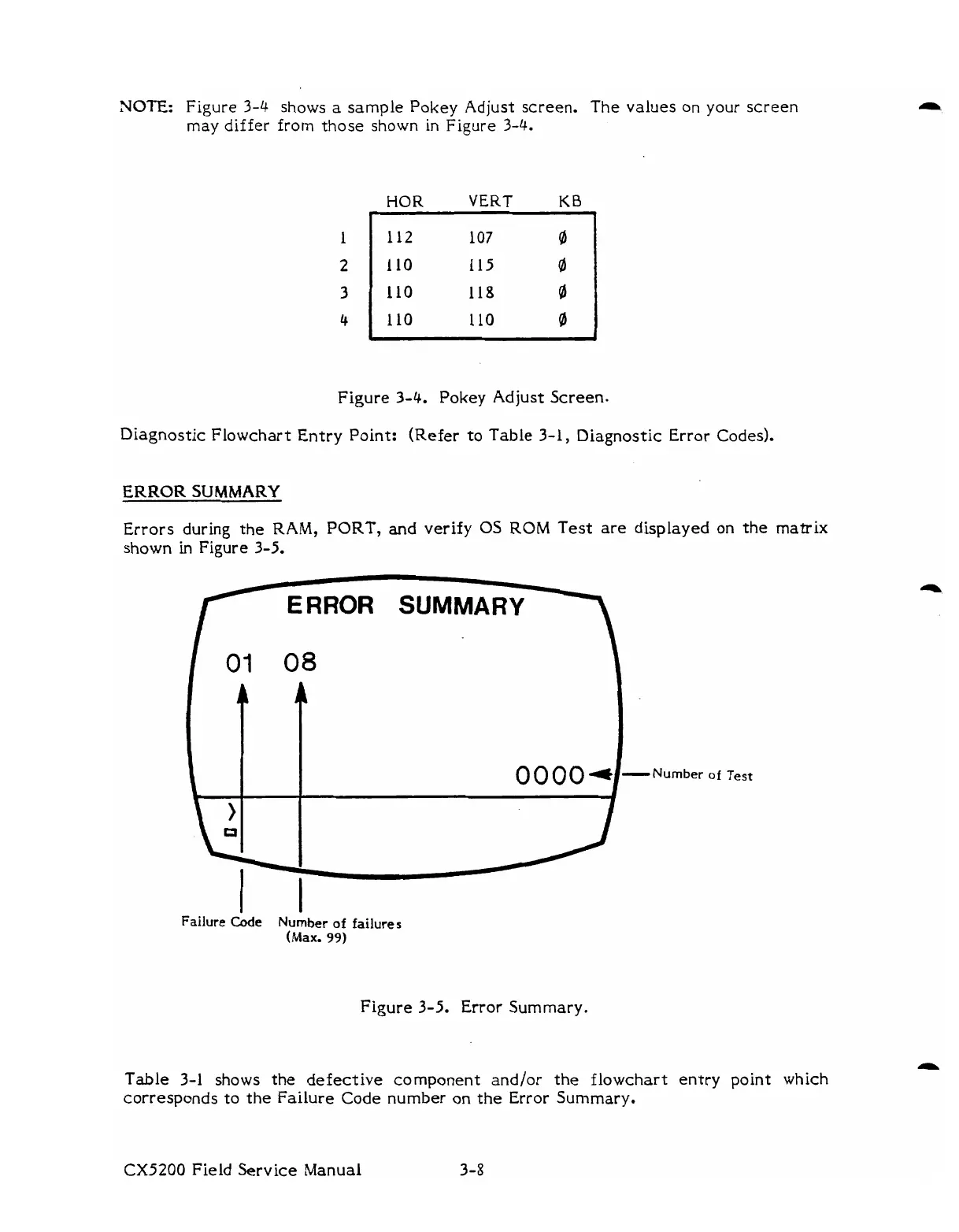
NOTE:
Figure
3-4
shows
a
sample Pokey Adjust screen.
The
values
on
your screen
may
differ from those shown in Figure
3-4.
HOR
VERT
KB
I
Figure 3-4. Pokey Adjust Screen-
Diagnostic Flowchart Entry Point: (Refer
to
Table 3-1, Diagnostic Error codes).
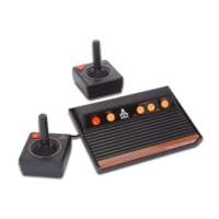
ERROR
SUMMARY
Errors during the
RAM,
PORT, and verify
05
ROM
Test are displayed on
the
matrix
shown
in
~i~ire 3-5.
RROR
SUMMARY
Failure
Code Number
of
failures
(Max.
99)
Figure 3-5. Error Summary.
-Number
of
Test
Table 3-1
shows the defective component and/or the flowchart entry point which
corresponds to the Failure Code number on the Error Summary.
CX5200
Field Service Manual
3-8