0
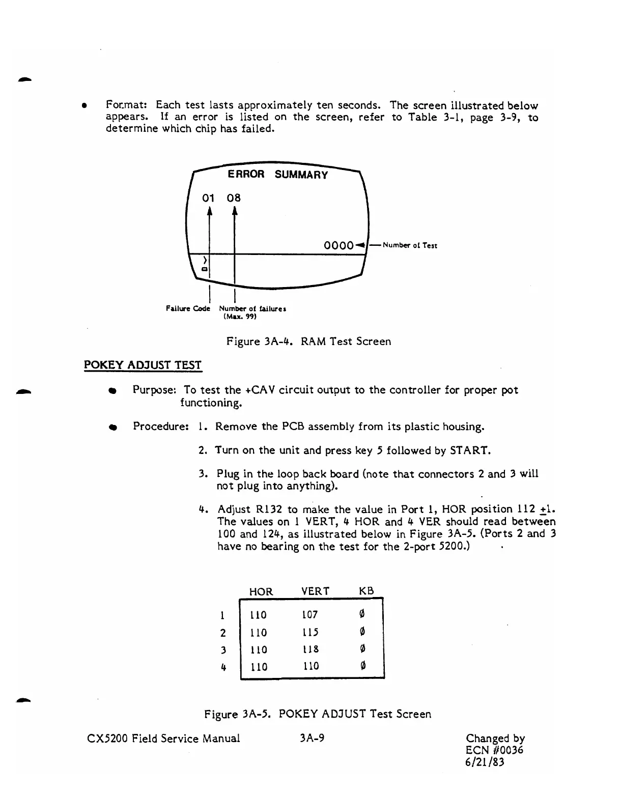
For-mat: Each test lasts approximately ten seconds. The screen illustrated below
appears.
If
an error
is
listed on the screen, refer to Table
3-1,
page 3-9, to
determine which chip has failed.
ERROR
SUMM
Number
of
Tert
Failure
cod=
Number
of
failures
(Mu.
99)
Figure 3A-4. RAM Test Screen
POKEY
ADJUST TEST
Purpose: To test
the
+CAV
circuit output to the controller for proper
pot
functioning.
Procedure: 1. Remove the PCB assembly from its plastic housing.
2.
Turn on the unit and press key
5
followed
by
START.
3.
Plug in
the
loop back board (note that connectors 2 and
3
will
not plug into anything).
4.
Adjust R132 to make the value in Port 1,
HOR
position 112 21.
The values on 1 VERT,
4 HOR
and
4
VER should read between
100 and 124, as illustrated below in Figure 3A-5. (Ports 2 and
3
have no bearing on the
test
for the 2-port
5200.)
Figure 3A-5.
POKEY
ADJUST Test Screen
HOR
VERT
KB
CX5200
Field Service Manual
3A-9
1
2
3
4
Changed by
ECN
#0036
6/21
/83
C
110
107
8
110
~15
8
110
118
8
110 110
0