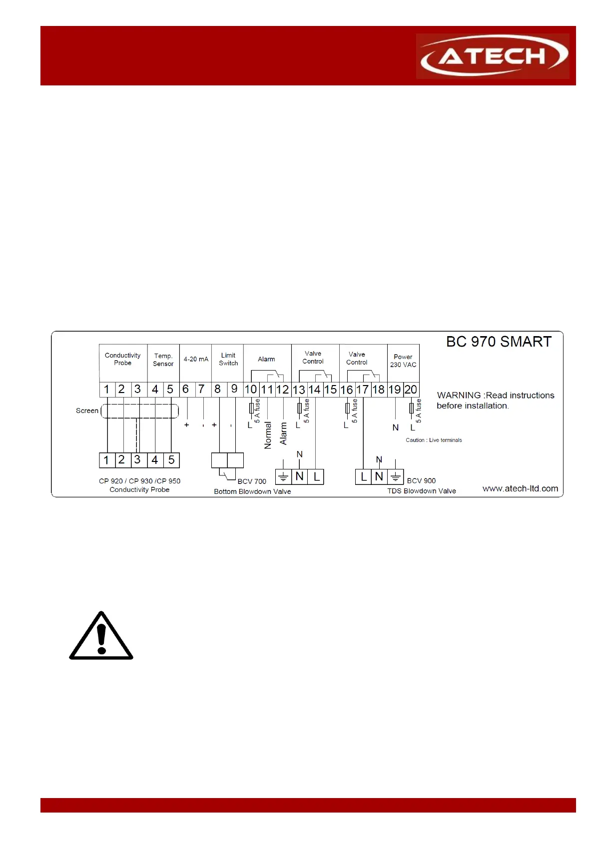
SMART TDS & BOTTOM BLOWDOWN CONTROLLER
Please refer to "BCV 900 Installation and Operation Manual for Automatic TDS Blowdown Control Valve" and
"CP 920, CP 930 or CP 950 Installation and Operation Manual for Conductivity Probe" for detailed information
Wiring between controller BC 970 and TDS blowdown valve actuator, 3x1 mm
2
cable can be used. Wiring between
controller BC 970 and conductivity probe, 5x1 mm
2
screened (shielded) - (LIYCY) cable can be used.
Wiring between controller BC 970 and namur solenoid valve, 3x1 mm
2
TTR cable can be used. Wiring between
controller BC 970 and limit switch, 2x1 mm
2
TTR normal cable can be used.
The locations of terminals should not be changed. If it is considered that the controller has phase connetiction
to terminal 10 to terminal 20, then the terminal 1 through 9 of the controller should never be connected to the
terminal 10 through terminal 20. Otherwise, this could cause damage to equipment and even damage to people.
Figure 4 Combi TDS Blowdown and Bottom Blowdown Controller BC 970 electrical connection diagram for
Note: Relays shown in de-energised state.
At the all phase inputs of the controller, must be used 3A fuse (non-delay type).