Chapter 1 – Installation of the instrument
UM-23100B-U User manual ATEQ F CLASS Page 14/90
2.2.1. 5) J4 Connector
Used for connection of the power supply.
The voltage must be 24 V DC with minimum current 1.25 A.
The instrument can be supplied from the J3 connector relay
board on the 24 V DC pin.
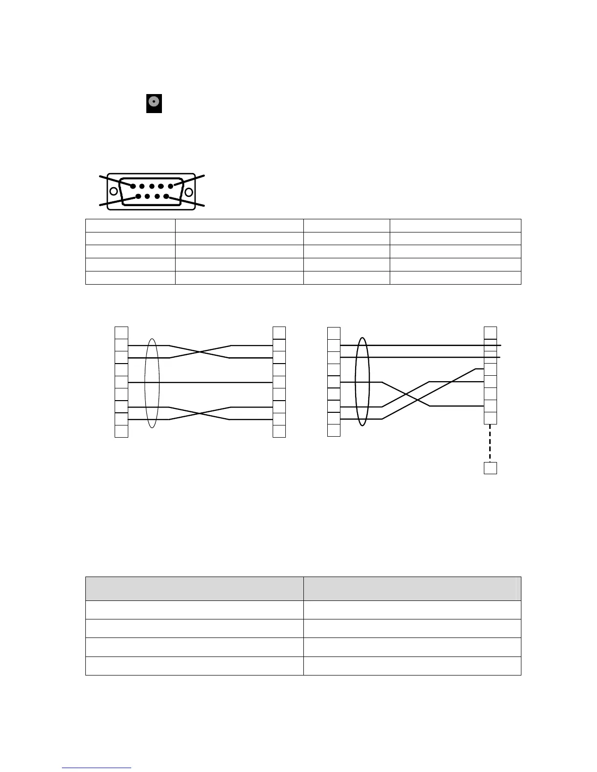
2.2.1. 6) J8 Connector (RS232)
1
5
9
6
Used for connection of a printer, a bar-code reader, a PC or
a memory module.
PIN 1 Not used PIN 6 Not used
PIN 2 RXD Data reception PIN 7 RTS (Request to send)
PIN 3 TXD Data emission PIN 8 CTS (Clear to send)
PIN 4 Not used PIN 9 Not used
PIN 5 Earth
2.2.1. 7) Examples of RS232 cables
1
2
3
4
5
6
7
8
9
1
2
3
4
5
6
7
8
9
ATEQ
Operator
9 pin SubD
connector
9 pin SubD
connector
RX
TX
GND
RTS
CTS
RX
TX
GND
RTS
CTS
1
2
3
4
5
6
7
8
9
1
2
3
4
5
6
7
8
ATEQ
Operator
25
9 pin SubD
connector
25 pin SubD
connector
RX
TX
GND
RTS
CTS
RX
TX
GND
RTS
CTS
2.2.2. Pneumatic connectors
Pneumatic connectors can be on the front or rear panels of the F CLASS instrument.
On the F CLASS instrument the connectors are only on the underside.
These pneumatic outputs may take on the functionalities shown below depending on
the configuration requested when the instrument was purchased.
"Automatic connector A" output "Automatic connector B" output
Automatic connector A Automatic connector B
Automatic connector A Marking (output code 1 used)
Automatic connector A External dump (output code 2 used)
Marking (output code 1 used) Dump (output code 2 used)